Background
The Nodal Scene Interface (ɴsɪ) was developed to replace existing APIs in the 3Delight renderer which were showing their age. Particualry the RenderMan Interface and the RenderMan Shading Language.
Having been designed in the 80s and extended several times since, they include features which are no longer relevant and design decisions which do not reflect modern needs.
This makes some features more complex to use than they should be and prevents or greatly increases the complexity of implementing other features.
The design of the ɴsɪ was shaped by multiple goals:
- Simplicity — The interface itself should be simple to understand and use, even if complex things can be done with it. This simplicity is carried into everything which derives from the interface.
- Interactive Rendering and Scene Edits — Scene edit operations should not be a special case. There should be no difference between scene description and scene edits. In other words, a scene description is a series of edits and vice versa.
- Tight Integration with Open Shading Language — ᴏsʟ integration is not superficial and affects scene definition. For example, there are no explicit light sources in ɴsɪ: light sources are created by connecting shaders with an
emission()closure to a geometry. - Scripting — The interface should be accessible from a platform independent, efficient and easily accessible scripting language. Scripts can be used to add render time intelligence to a given scene description.
- Performance and Multi-Threading — All API design decisions are made with performance in mind and this includes the possibility to run all API calls in a concurrent, multi-threaded environment. Nearly all software today which deals with large data sets needs to use multiple threads at some point. It is important for the interface to support this directly so it does not become a single thread communication bottleneck. This is why commands are self-contained and do not rely on a current state. Everything which is needed to perform an action is passed in on every call.
- Support for Serialization — The interface calls should be serializable. This implies a mostly unidirectional dataflow from the client application to the renderer and allows greater implementation flexibility.
- Extensibility — The interface should have as few assumptions as possible built-in about which features the renderer supports. It should also be abstract enough that new features can be added without looking out of place.
The Interface
The Interface Abstraction
The Nodal Scene Interface is built around the concept of nodes. Each node has a unique handle to identify it and a type which describes its intended function in the scene. Nodes are abstract containers for data. The interpretation depends on the node type. Nodes can also be connected to each other to express relationships.
Data is stored on nodes as attributes. Each attribute has a name which is unique on the node and a type which describes the kind of data it holds (strings, integer numbers, floating point numbers, etc).
Relationships and data flow between nodes are represented as connections. Connections have a source and a destination. Both can be either a node or a specific attribute of a node. There are no type restrictions for connections in the interface itself. It is acceptable to connect attributes of different types or even attributes to nodes. The validity of such connections depends on the types of the nodes involved.
What we refer to as the ɴsɪ has two major components:
- Methods to create nodes, attributes and their connections.
- Node types understood by the renderer.
Much of the complexity and expressiveness of the interface comes from the supported nodes. The first part was kept deliberately simple to make it easy to support multiple ways of creating nodes. We will list a few of those in the following sections but this list is not meant to be final. New languages and file formats will undoubtedly be supported in the future.
APIs
The C API
This section describes the C implementation of the ɴsɪ, as provided in the nsi.h file. This will also be a reference for the interface in other languages as all concepts are the same.
#define NSI_VERSION 1
The NSI_VERSION macro exists in case there is a need at some point to break source compatibility of the C interface.
#define NSI_SCENE_ROOT ".root"
The NSI_SCENE_ROOT macro defines the handle of the root node.
#define NSI_ALL_NODES ".all"
The NSI_ALL_NODES macro defines a special handle to refer to all nodes in some contexts, such as removing connections.
#define NSI_ALL_ATTRIBUTES ".all"
The NSI_ALL_ATTRIBUTES macro defines a special handle to refer to all attributes in some contexts, such as removing connections.
Context Handling
NSIContext_t NSIBegin(
   int n_params,
   const NSIParam_t *args
)
void NSIEnd(
   NSIContext_t ctx
)
These two functions control creation and destruction of a ɴsɪ context, identified by a handle of type NSIContext_t.
A context must be given explicitly when calling all other functions of the interface. Contexts may be used in multiple threads at once. The NSIContext_t is a convenience typedef and is defined as:
typedef int NSIContext_t;
If NSIBegin fails for some reason, it returns NSI_BAD_CONTEXT which is defined in nsi.h:
#define NSI_BAD_CONTEXT ((NSIContext_t)0)
Optional arguments may be given to NSIBegin() to control the creation of the context:
| Name | Type | Description/Values |
|---|---|---|
type | string | Sets the type of context to create. The possible types are: |
render — Execute the calls directly in the renderer. This is the default. | ||
apistream — To write the interface calls to a stream, for later execution. The target for writing the stream must be specified in another argument. | ||
streamfilename | string | The file to which the stream is to be output, if the context type is apistream. Specify stdout to write to standard output and stderr to write to standard error. |
streamformat | string (nsi) | The format of the command stream to write. Possible formats are: |
nsi — Produces an ɴsɪ stream. | ||
binarynsi — Produces a binary encoded ɴsɪ stream. | ||
autonsi — Behaves like nsi if streamfilename ends with .nsia, and like binarynsi otherwise. | ||
streamcompression | string | The type of compression to apply to the written command stream. |
streampathreplacement | int (1) | Use 0 to disable replacement of path prefixes by references to environment variables which begin with NSI_PATH_ in an ɴsɪ stream. This should generally be left enabled to ease creation of files which can be moved between systems. |
separateprocess | int (0) | A non-zero value makes rendering occur in a separate process. This can reduce the effect of rendering on the host application. |
errorhandler | pointer | A function which is to be called by the renderer to report errors. The default handler will print messages to the console. |
errorhandlerdata | pointer | The userdata argument of the error reporting function. |
executeprocedurals | string | A list of procedural types that should be executed immediately when a call to NSIEvaluate() or a procedural node is encountered and NSIBegin()’s output type is apistream. This will replace any matching call to NSIEvaluate() with the results of the procedural’s execution. |
Arguments vs. Attributes
Arguments are what a user specifies when calling a function of the API. Each function takes extra, optional arguments.
Attributes are properties of nodes and are only set through the aforementioned optional arguments using the NSISetAttribute() and NSISetAttributeAtTime() functions.
Optional Arguments
Any API call can take extra arguments. These are always optional. What this means the call can do work without the user specifying these arguments.
Nodes are special as they have mandatory extra attributes that are set after the node is created inside the API but which must be set before the geometry or concept the node represents can actually be created in the scene.
These attributes are passed as extra arguments to the NSISetAttribute() and NSISetAttributeAtTime() functions.
[!NOTE] Nodes can also take extra arguments when they are created. These optional arguments are only meant to add information needed to create the node that a particular implementation may need.
As of this writing there is no implementation that has any such optional arguments on the
NSICreate()function. The possibility to specify them is solely there to make the API future proof.
[!CAUTION] Nodes do not have optional arguments for now. An optional argument on a node is not the same as an attribute on a node.
Attributes — Describe the Node’s Specifics
Attributes are only for nodes. They must be set using the NSISetAttribute() or NSISetAttributeAtTime() functions.
They can not be set on the node when it is created with the NSICreate() function.
[!CAUTION] Only nodes have attributes. They are sent to the API via optional arguments on the API’s attribute functions.
Passing Optional Arguments
struct NSIParam_t
{
    const char *name;
    const void *data;
    int type;
    int arraylength;
    size_t count;
    int flags;
};
This structure is used to pass variable argument lists through the C interface. Most functions accept an array of the structure in a args argument along with its length in a n_params argument.
The meaning of these two arguments will not be documented for every function. Instead, each function will document the arguments which can be given in the array.
name
: A C string which gives the argument’s name.
type
: Identifies the argument’s type, using one of the following constants:
| Constant | Description |
|---|---|
NSITypeFloat | Single 32-bit floating point value. |
NSITypeDouble | Single 64-bit floating point value. |
NSITypeInteger | Single 32-bit integer value. |
NSITypeInt64 | Single 64-bit integer value. |
NSITypeString | String value, given as a pointer to a C string. |
NSITypeColor | Color, given as three 32-bit floating point values. |
NSITypePoint | Point, given as three 32-bit floating point values. |
NSITypeVector | Vector, given as three 32-bit floating point values. |
NSITypeNormal | Normal vector, given as three 32-bit floating point values. |
NSITypeMatrix | Transformation matrix, in row-major order, given as 16 32-bit floating point values. |
NSITypeDoubleMatrix | Transformation matrix, in row-major order, given as 16 64-bit floating point values. |
NSITypePointer | C pointer. |
NSITypeHPoint | Homogeneous point (w·x, w·y, w·z, w), given as four 32-bit floating point values. The stream spells it hpoint. See Geometry in the Type System for the draft name weighted-point. |
[!NOTE] The names of these constants spell the storage width in three different ways. See Type Names: API Alternatives for a draft that reworks them.
Tuple types are specified by setting the bit defined by the NSIParamIsArray constant in the flags member and the length of the tuple in the arraylength member.
[!TIP] It helps to view
arraylengthas a part of the data type. The data type is a tuple with this length whenNSIParamIsArrayis set.
[!NOTE] If
NSIParamIsArrayis not set,arraylengthis ignored.The
NSIParamIsArrayflag is necessary to distinguish between arguments that happen to be of length 1 (set in thecountmember) and tuples that have a length of 1 (set in thearraylengthmember) for the resp. argument."foo" "int[1]" 1 [42] # The answer to the ultimate question – in a (single) tuple "bar" "int" 1 13 # My favorite Friday
The count member gives the number of data items given as the value of the argument.
The data member is a pointer to the data for the argument. This is a pointer to a single value or a number of values. Depending on type, count and arraylength settings.
[!NOTE] When data is an array, the actual number of elements in the array is count × arraylength × n. Where n is specified implicitly through the
typemember in the table above.For example, if the type is
NSITypeColor(3 values),NSIParamIsArrayis set,arraylengthis 2 andcountis 4,datais expected to contain 24 32-bit floating point values (3×2×4).
The flags member is a bit field with a number of constants used to communicate more information about the argument:
| Flag | Description |
|---|---|
NSIParamIsArray | To specify that the argument is an array type, as explained above. |
NSIParamPerFace | To specify that the argument has different values for every face of a geometric primitive, where this might be ambiguous. |
NSIParamPerVertex | Specify that the argument has different values for every vertex of a geometric primitive, where this might be ambiguous. |
NSIParamInterpolateLinear | Specify that the argument is to be interpolated linearly instead of using some other, default method. |
[!NOTE]
NSIParamPerFaceorNSIParamPerVertexare only strictly needed in rare circumstances when a geometric primitive’s number of vertices matches the number of faces. The most simple case is a tetrahedral mesh which has exactly four vertices and also four faces.
Indirect lookup of arguments is achieved by giving an integer argument of the same name, with the .indices suffix added. This is read to know which values of the other argument to use.
Create "subdiv" "mesh"
SetAttribute "subdiv"
  "nvertices" "int" 4 [ 4 4 4 4 ]
  "P" "point" 9 [
    0 0 0  1 0 0  2 0 0
    0 1 0  1 1 0  2 1 0
    0 2 0  1 2 0  2 2 2 ]
  "P.indices" "int" 16 [
    0 1 4 3  2 3 5 4  3 4 7 6  4 5 8 7 ]
  "subdivision.scheme" "string" 1 "catmull-clark"
Node Creation
void NSICreate(
    NSIContext_t context,
    NSIHandle_t handle,
    const char *type,
    int n_params,
    const NSIParam_t *args
)
This function is used to create a new node. Its arguments are:
context
: The context returned by NSIBegin(). See context handling.
handle
: A node handle. This string will uniquely identify the node in the scene.
If the supplied handle matches an existing node, the function does nothing if all other arguments match the call which created that node. Otherwise, it emits an error. Note that handles need only be unique within a given interface context. It is acceptable to reuse the same handle inside different contexts. The NSIHandle_t typedef is defined in nsi.h:
typedef const char* NSIHandle_t;
type
: The type of node to create.
n_params, args
: This pair describes a list of optional arguments. The NSIParam_t type is described in this section.
[!CAUTION] There are no optional arguments defined as of now.
void NSIDelete(
    NSIContext_t ctx,
    NSIHandle_t handle,
    int n_params,
    const NSIParam_t *args
)
This function deletes a node from the scene. All connections to and from the node are also deleted. Note that it is not possible to delete the root or the global node. Its arguments are:
context
: The context returned by NSIBegin(). See context handling.
handle
: A node handle. It identifies the node to be deleted.
It accepts the following optional arguments:
| Name | Type | Description/Values |
|---|---|---|
recursive | int | Specifies whether deletion is recursive. By default, only the specified node is deleted. If a value of 1 is given, then nodes which connect to the specified node are recursively removed unless they also have connections which do not eventually lead to the specified node, or their connection to the deleted node was created with a strength greater than 0. This allows, for example, deletion of an entire shader network in a single call. |
Setting Attributes
void NSISetAttribute(
    NSIContext_t ctx,
    NSIHandle_t object,
    int n_params,
    const NSIParam_t *args
)
This function sets attributes on a previously created node. All optional arguments of the function become attributes of the node.
On a shader node, this function is used to set the implicitly defined shader arguments.
Setting an attribute using this function replaces any value previously set by NSISetAttribute() or NSISetAttributeAtTime(). To reset an attribute to its default value, use NSIDeleteAttribute().
void NSISetAttributeAtTime(
    NSIContext_t ctx,
    NSIHandle_t object,
    double time,
    int n_params,
    const NSIParam_t *args
)
This function sets time-varying attributes (i.e. motion blurred). The time argument specifies at which time the attribute is being defined.
It is not required to set time-varying attributes in any particular order. In most uses, attributes that are motion blurred must have the same specification throughout the time range.
A notable exception is the P attribute on particles which can be of different size for each time step because of appearing or disappearing particles. Setting an attribute using this function replaces any value previously set by NSISetAttribute().
void NSIDeleteAttribute(
    NSIContext_t ctx,
    NSIHandle_t object,
    const char *name
)
This function deletes any attribute with a name which matches the name argument on the specified object. There is no way to delete an attribute only for a specific time value.
Deleting an attribute resets it to its default value.
For example, after deleting the transformationmatrix attribute on a transform node, the transform will be an identity. Deleting a previously set attribute on a shader node will default to whatever is declared inside the shader.
Making Connections
void NSIConnect(
    NSIContext_t ctx,
    NSIHandle_t from,
    const char *from_attr,
    NSIHandle_t to,
    const char *to_attr,
    int n_params,
    const NSIParam_t *args
)
void NSIDisconnect(
    NSIContext_t ctx,
    NSIHandle_t from,
    const char *from_attr,
    NSIHandle_t to,
    const char *to_attr
)
These two functions respectively create or remove a connection between two elements. It is not an error to create a connection which already exists or to remove a connection which does not exist but the nodes on which the connection is performed must exist. The arguments are:
from
: The handle of the node from which the connection is made.
from_attr
: The name of the attribute from which the connection is made. If this is an empty string then the connection is made from the node instead of from a specific attribute of the node.
to
: The handle of the node to which the connection is made.
to_attr
: The name of the attribute to which the connection is made. If this is an empty string then the connection is made to the node instead of to a specific attribute of the node.
NSIConnect() accepts additional optional arguments.
| Name | Type | Description/Values |
|---|---|---|
value | This can be used to change the value of a node’s attribute in some contexts. Refer to guidelines on inter-object visibility for more information about the utility of this parameter. | |
priority | int (0) | When connecting attribute nodes, indicates in which order the nodes should be considered when evaluating the value of an attribute. At equal priority, the attributes node connected first wins; see the attributes node. |
strength | int (0) | A connection with a strength greater than 0 will block the progression of a recursive NSIDelete. |
Severing Connections
With NSIDisconnect(), the handle for either node, and any or all of the attribute names, may be the special value .all. This will remove all connections which match the other arguments. For example, to disconnect everything from the scene’s root:
NSIDisconnect( NSI_ALL_NODES, "", NSI_SCENE_ROOT, "objects" );
Evaluating Procedurals
void NSIEvaluate(
    NSIContext_t ctx,
    int n_params,
    const NSIParam_t *args
)
This function includes a block of interface calls from an external source into the current scene. It blends together the concepts of a straight file include, commonly known as an archive, with that of procedural include which is traditionally a compiled executable. Both are really the same idea expressed in a different language (note that for delayed procedural evaluation one should use the procedural node).
The ɴsɪ adds a third option which sits in-between — Lua scripts. They are much more powerful than a simple included file yet they are also much easier to generate as they do not require compilation. It is, for example, very realistic to export a whole new script for every frame of an animation. It could also be done for every character in a frame. This gives great flexibility in how components of a scene are put together.
The ability to load ɴsɪ commands straight from memory is also provided.
The optional arguments accepted by this function are:
| Name | Type | Description/Values |
|---|---|---|
type | string | The type of file which will generate the interface calls. This can be one of: |
apistream — Read in an ɴsɪ stream. This requires either filename, script or buffer/size to be provided as the source of the ɴsɪ commands. | ||
lua — Execute a Lua script, either from file or inline. See also how to evaluate a Lua script. | ||
dynamiclibrary — Execute native compiled code in a loadable library. See dynamic library procedurals for an implementation example. | ||
filename | string | The file from which to read the interface stream. |
replacensidir | int (1) | When evaluating an apistream, this controls whether ${NSIDIR} references are replaced by the path to the directory that holds filename. |
script | string | A valid Lua script to execute when type is set to lua. |
buffer/size | pointer/int64 | These two arguments define a memory block that contains ɴsɪ commands to execute. |
backgroundload | int | If this is nonzero, the object may be loaded in a separate thread, at some later time. This requires that further interface calls not directly reference objects defined in the included file. The only guarantee is that the file will be loaded before rendering begins. |
Error Reporting
enum NSIErrorLevel
{
    NSIErrMessage = 0,
    NSIErrInfo = 1,
    NSIErrWarning = 2,
    NSIErrError = 3
}
typedef void (*NSIErrorHandler_t)(
    void *userdata, int level, int code, const char *message
)
This defines the type of the error handler callback given to the NSIBegin() function. When it is called, the level argument is one of the values defined by the NSIErrorLevel enum. The code argument is a numeric identifier for the error message, or 0 when irrelevant. The message argument is the text of the message.
The text of the message will not contain the numeric identifier nor any reference to the error level. It is usually desirable for the error handler to present these values together with the message. The identifier exists to provide easy filtering of messages.
The intended meaning of the error levels is as follows:
| Level | Description |
|---|---|
NSIErrMessage | For general messages, such as may be produced by printf() in shaders. The default error handler will print this type of messages without an eol terminator as it’s the duty of the caller to format the message. |
NSIErrInfo | For messages which give specific information. These might simply inform about the state of the renderer, files being read, settings being used and so on. |
NSIErrWarning | For messages warning about potential problems. These will generally not prevent producing images and may not require any corrective action. They can be seen as suggestions of what to look into if the output is broken but no actual error is produced. |
NSIErrError | For error messages. These are for problems which will usually break the output and need to be fixed. |
Rendering
void NSIRenderControl(
    NSIContext_t ctx,
    int n_params,
    const NSIParam_t *args
)
This function is the only control function of the API. It is responsible for starting, suspending and stopping the render. It also allows for synchronizing the render with interactive calls that might have been issued. The function accepts:
| Name | Type | Description/Values |
|---|---|---|
action | string | Specifies the operation to be performed, which should be one of the following: |
start — This starts rendering the scene in the provided context. The render starts in parallel and the control flow is not blocked. | ||
wait — Wait for a render to finish. | ||
synchronize — For an interactive render, apply all the buffered calls to scene’s state. | ||
suspend — Suspends render in the provided context. | ||
resume — Resumes a previously suspended render. | ||
stop — Stops rendering in the provided context without destroying the scene. |
NSIRenderControl() accepts the following optional arguments:
| Name | Type | Description/Values |
|---|---|---|
progressive | int (0) | If set to 1, render the image in a progressive fashion. |
interactive | int (0) | If set to 1, the renderer will accept commands to edit scene’s state while rendering. The difference with a normal render is that the render task will not exit even if rendering is finished. Interactive renders are by definition progressive. Interactive renders are by definition progressive. |
frame | Specifies the frame number of this render. | |
stoppedcallback | pointer | A pointer to a user function that should be called on rendering status changes. The function signature is: |
void StoppedCallback(
    void* stoppedcallbackdata,
    NSIContext_t ctx,
    int status
)
The status argument can take the following values:
NSIRenderCompletedindicates that rendering has completed normally.NSIRenderAbortedindicates that rendering was interrupted before completion.NSIRenderSynchronizedindicates that an interactive render has produced an image which reflects all changes to the scene.NSIRenderRestartedindicates that an interactive render has received new changes to the scene and no longer has an up to date image.
| Name | Type | Description/Values |
|---|---|---|
stoppedcallbackdata | pointer | A pointer that will be passed back to the stoppedcallback function. |
The C++ API
The nsi.hpp file provides C++ wrappers which are less tedious to use than the low level C interface. All the functionality is inline so no additional libraries are needed and there are no abi issues to consider.
Creating a Context
The core of these wrappers is the NSI::Context class. Its default construction will require linking with the renderer.
#include "nsi.hpp"

NSI::Context nsi;
The nsi_dynamic.hpp file provides an alternate api source which will load the renderer at runtime and thus requires no direct linking.
#include "nsi.hpp"
#include "nsi_dynamic.hpp"

NSI::DynamicAPI nsi_api;
NSI::Context nsi(nsi_api);
In both cases, a new nsi context can then be created with the Begin() method.
nsi.Begin();
This will be bound to the NSI::Context object and released when the object is deleted. It is also possible to bind the object to a handle from the C API, in which case it will not be released unless the End() method is explicitly called.
Argument Passing
The NSI::Context class has methods for all the other ɴsɪ calls. The optional arguments of those can be set by several accessory classes and given in many ways. The most basic is a single argument.
nsi.SetAttribute("handle", NSI::FloatArg("fov", 45.0f));
It is also possible to provide static lists:
nsi.SetAttribute(
    "handle",(
        NSI::FloatArg("fov", 45.0f),
        NSI::DoubleArg("depthoffield.fstop", 4.0)
    )
);
And finally a class supports dynamically building a list.
NSI::ArgumentList args;
args.Add(new NSI::FloatArg("fov", 45.0f));
args.Add(new NSI::DoubleArg("depthoffield.fstop", 4.0));
nsi.SetAttribute("handle", args);
The NSI::ArgumentList object will delete all the objects added to it when it is deleted.
Argument Classes
To be continued …
The Rust API
The nsi crate provides Rust wrappers for the ɴsɪ API. These are based on the low-level wrapper crate nsi-sys that contains autogenerated bindings on top of nsi.h.
Creating a Context
The core of these wrappers is the Context struct. Its construction triggers dynamic linking with the renderer.
#![allow(unused)]
fn main() {
let ctx = nsi::Context::new(None)?
}
The Lua API
The scripted interface is slightly different than its counterpart since it has been adapted to take advantage of the niceties of Lua. The main differences with the C API are:
- No need to pass a ɴsɪ context to function calls since it’s already embodied in the ɴsɪ Lua table (which is used as a class).
- The
typeargument can be omitted if the argument is an integer, real or string (as with theKdandfilenamein the example below). - ɴsɪ arguments can either be passed as a variable number of arguments or as a single argument representing an array of arguments (as in the
"ggx"shader below) - There is no need to call
NSIBegin()andNSIEnd()equivalents since the Lua script is run in a valid context.
Below is an example shader creation logic in Lua.
nsi.Create( "lambert", "shader" );
nsi.SetAttribute(
    "lambert",
    { name = "filename", data = "lambert_material.oso" },
    { name = "Kd", data = 0.55 },
    { name = "albedo", data = { 1, 0.5, 0.3 }, type = nsi.TypeColor }
);

nsi.Create( "ggx", "shader" );
nsi.SetAttribute(
    "ggx", {
        {name = "filename", data = "ggx_material.oso" },
        {name = "anisotropy_direction", data = {0.13, 0 ,1}, type = nsi.TypeVector }
    }
);
API Calls
All (in a scripting context) useful ɴsɪ functions are provided and are listed below. There is also a nsi.utilities class which, for now, only contains a method to print errors.
| Lua Function | C equivalent |
|---|---|
nsi.SetAttribute() | NSISetAttribute() |
nsi.SetAttributeAtTime() | NSISetAttributeAtTime() |
nsi.Create() | NSICreate() |
nsi.Delete() | NSIDelete() |
nsi.DeleteAttribute() | NSIDeleteAttribute() |
nsi.Connect() | NSIConnect() |
nsi.Disconnect() | NSIDisconnect() |
Evaluate() | NSIEvaluate() |
ɴsɪ functions
Optional Function Arguments Format
Each single argument is passed as a Lua table containing the following key values:
-
name– the name of the argument. -
data– the argument data. Either a value (integer, float or string) or an array. -
type– the type of the argument. Possible values are:Lua Type C equivalent nsi.TypeFloatNSITypeFloatnsi.TypeIntegerNSITypeIntegernsi.TypeStringNSITypeStringnsi.TypeColorNSITypeColornsi.TypeNormalNSITypeNormalnsi.TypeVectorNSITypeVectornsi.TypePointNSITypePointnsi.TypeMatrixNSITypeMatrixnsi.TypeDoubleMatrixNSITypeDoubleMatrixnsi.TypeHPointNSITypeHPointLua ɴsɪ argument types
NSITypeDouble,NSITypeInt64, andNSITypePointerhave no Lua equivalent. Use the C or C++ API for those types.Warning: In 3Delight 2.9.210,
nsi.TypeDouble,nsi.TypeInt64andnsi.TypePointerarenil. An argument that names one of them has no type, so the renderer infers one, and the value is changed without an error:data=9007199254740993, type=nsi.TypeInt64arrives as theint1, anddata=0.1, type=nsi.TypeDoublearrives as afloat. -
arraylength– length of the array for each element.
Here are some example of well formed arguments:
--[[ strings, floats and integers do not need a 'type' specifier ]] --
p1 = {
    name = "shaderfilename",
    data = "emitter"
};
p2 = {
    name = "power",
    data = 10.13
};
p3 = {
    name = "toggle",
    data = 1
};

--[[ All other types, including colors and points, need a
     type specified for disambiguation. ]]--
p4 = {
    name = "Cs",
    data = { 1, 0.9, 0.7 },
    type=nsi.TypeColor
};

--[[ An array of 2 colors ]] --
p5 = {
    name = "vertex_color",
    arraylength = 2,
    data= { 1, 1, 1, 0, 0, 0 },
    type= nsi.TypeColor
};

--[[ Create a simple mesh and connect it root ]] --
nsi.Create( "floor", "mesh" )
nsi.SetAttribute(
    "floor", {
        name = "nvertices",
        data = 4
    }, {
        name = "P",
        type = nsi.TypePoint,
        data = { -2, -1, -1, 2, -1, -1, 2, 0, -3, -2, 0, -3 }
    }
)
nsi.Connect( "floor", "", ".root", "objects" )
Evaluating a Lua Script
Script evaluation is done through C, an ɴsɪ stream or even another Lua script. Here is an example using an ɴsɪ stream:
Evaluate
    "filename" "string" 1 ["test.nsi.lua"]
    "type" "string" 1 ["lua"]
It is also possible to evaluate a Lua script inline using the script argument. For example:
Evaluate
    "script" "string" 1 ["nsi.Create(\"light\", \"shader\");"]
    "type" "string" 1 ["lua"]
Both filename and script can be specified to NSIEvaluate() in one go, in which case the inline script will be evaluated before the file and both scripts will share the same ɴsɪ and Lua contexts.
Any error during script parsing or evaluation will be sent to ɴsɪ’s error handler.
Some utilities, such as error reporting, are available through the nsi.utilities class.
[!NOTE] All Lua scripts are run in a sandbox in which all Lua system libraries are disabled.
Passing Arguments to a Lua Script
All arguments passed to NSIEvaluate() will appear in the nsi.scriptparameters table. For example, the following call:
Evaluate
    "filename" "string" 1 ["test.lua"]
    "type" "string" 1 ["lua"]
    "userdata" "color[2]" 1 [1 0 1 2 3 4]
Will register a userdata entry in the nsi.scriptparameters table. So executing the following line in the test.lua script that the above snippete references:
print( nsi.scriptparameters.userdata.data[5] );
Will print:
3.0
Reporting Errors from a Lua Script
Use nsi.utilities.ReportError() to send error messages to the error handler defined in the current nsi context. For example:
nsi.utilities.ReportError( nsi.ErrWarning, "Watch out!" );
The error codes are the same as in the C API. They are shown in the table below.
| Lua Error Codes | C equivalent |
|---|---|
nsi.ErrMessage | NSIErrMessage |
nsi.ErrWarning | NSIErrWarning |
nsi.ErrInfo | NSIErrInfo |
nsi.ErrError | NSIErrError |
Lua ɴsɪ error codes
The Python API
The nsi.py file provides a python wrapper to the C interface. It is compatible with both Python 2.7 and Python 3.
An example of how to us it is provided in python/examples/live_edit/live_edit.py.
Precision of Untyped Arguments
The wrapper infers a type when you do not give one. A Python float becomes
NSITypeDouble, and a Python int becomes NSITypeInteger
(nsi.py, _GetArgNSIType).
The renderer matches attribute types exactly. It does not convert between
widths. An attribute declared float therefore rejects a bare Python float,
and warns:
3DL WARNING E6007 wrong type for attribute 'fov' on node 'c' of type
'perspectivecamera' (expected type 'float', got 'double')
The call is dropped, and the attribute keeps its previous value. Pass a
FloatArg for any attribute that the node reference documents as float:
nsi.SetAttribute("c", fov=nsi.FloatArg(35))
The shipped live_edit.py example does this for fov, and passes
shutterrange bare because that attribute is declared double.
The Interface Stream
It is important for a scene description API to be streamable. This allows saving scene description into files, communicating scene state between processes and provide extra flexibility when sending commands to the renderer 1.
Instead of re-inventing the wheel, the authors have decided to use exactly the same format as is used by the RenderMan Interface Bytestream (RIB). This has several advantages:
- Well defined ASCII and binary formats.
- The ASCII format is human readable and easy to understand.
- Easy to integrate into existing renderers (writers and readers already available).
Note that since Lua is part of the API, one can use Lua files for API streaming 2.
Footnotes
-
The streamable nature of the RenderMan API, through RIB, is an undeniable advantage. RenderMan is a registered trademark of Pixar. ↩
-
Preliminary tests show that the Lua parser is as fast as an optimized ASCII RIB parser. ↩
Dynamic Library Procedurals
NSIEvaluate and procedural nodes can execute code loaded from a dynamically loaded library that defines a procedural. Executing the procedural is expected to result in a series of ɴsɪ API calls that contribute to the description of the scene. For example, a procedural could read a part of the scene stored in a different file format and translate it directly into ɴsɪ calls.
This section describes how to use the definitions from the nsi_procedural.h header to write such a library in C or C++. However, the process of compiling and linking it is specific to each operating system and out of the scope of this manual.
Entry Point
The renderer expects a dynamic library procedural to contain a NSIProceduralLoad() symbol, which is an entry point for the library’s main function:
struct NSIProcedural_t* NSIProceduralLoad(
    NSIContext_t ctx,
    NSIReport_t report,
    const char* nsi_library_path,
    const char* renderer_version);
It will be called only once per render and has the responsibility of initializing the library and returning a description of the functions implemented by the procedural. However, it is not meant to generate ɴsɪ calls. For that reason, it is passed a unique NSIContext_t that should be used only in that function, usually to call the report function.
It returns a pointer to a descriptor struct of type NSIProcedural_t (see below).
NSIProceduralLoad() receives the following parameters:
| Name | Type | Description |
|---|---|---|
ctx | NSIContext_t | The ɴsɪ context into which the procedural is being loaded. |
report | NSIReport_t | A function that can be used to display informational, warning or error messages through the renderer. |
nsi_library_path | const char* | The path to the ɴsɪ implementation that is loading the procedural. This allows the procedural to explicitly make its ɴsɪ API calls through the same implementation (for example, by using NSI::DynamicAPI defined in nsi_dynamic.hpp). It’s usually not required if only one implementation of ɴsɪ is installed on the system. |
renderer_version | const char* | A character string describing the current version of the renderer. |
Procedural Description
typedef void (*NSIProceduralUnload_t)(
    NSIContext_t ctx,
    NSIReport_t report,
    struct NSIProcedural_t* proc);

typedef void (*NSIProceduralExecute_t)(
    NSIContext_t ctx,
    NSIReport_t report,
    struct NSIProcedural_t* proc,
    int nparams,
    const struct NSIParam_t* params);

struct NSIProcedural_t
{
    unsigned nsi_version;
    NSIProceduralUnload_t unload;
    NSIProceduralExecute_t execute;
};
The structure returned by NSIProceduralLoad() contains information needed by the renderer to use the procedural.
[!NOTE] The allocation of this structure is managed entirely from within the procedural and it will never be copied or modified by the renderer.
[!TIP] This means that it is possible for a procedural to extend the structure (by over-allocating memory or subclassing, for example) in order to store any extra information that it might need later.
The nsi_version member must be set to NSI_VERSION (defined in nsi.h), so the renderer is able to determine which version of ɴsɪ was used when compiling the procedural.
The function pointer types used in the definition are:
NSIProceduralUnload_tis a function that cleans-up after the last execution of the procedural. This is the dual ofNSIProceduralLoad(). In addition to argumentsctxandreport, also received byNSIProceduralLoad(), it receives the description of the procedural returned byNSIProceduralLoad().NSIProceduralExecute_tis a function that contributes to the description of the scene by generating ɴsɪ API calls. SinceNSIProceduralExecute_tmight be called multiple times in the same render, it’s important that it uses the contextctxit receives as a parameter to make its ɴsɪ calls, and not the context previously received byNSIProceduralLoad(). It also receives any extra parameters sent to NSIEvaluate, or any extra attributes set on a procedural node. They are stored in theparamsarray (of lengthnparams).NSIParam_tis described in passing optional arguments.
Error Reporting
All functions of the procedural called by ɴsɪ receive a parameter of type NSIReport_t. This is a pointer to a function which should be used by the procedural to report errors or display any informational message.
typedef void (*NSIReport_t)(
    NSIContext_t ctx, int level, const char* message);
It receives the current context, the error level (as described in error reporting) and the message to be displayed. This information will be forwarded to any error handler attached to the current context, along with other regular renderer messages. Using this, instead of a custom error reporting mechanism, will benefit the user by ensuring that all messages are displayed in a consistent manner.
Preprocessor Macros
Some convenient C preprocessor macros are also defined in nsi_procedural.h:
NSI_PROCEDURAL_UNLOAD(name)
and
NSI_PROCEDURAL_EXECUTE(name)
declare functions of the specified name that match NSIProceduralUnload_t and NSIProceduralExecute_t, respectively.
NSI_PROCEDURAL_LOAD
declares a NSIProceduralLoad function.
NSI_PROCEDURAL_INIT(proc, unload_fct, execute_fct)
initializes a NSIProcedural_t (passed as proc) using the addresses of the procedural’s main functions. It also initializes proc.nsi_version.
So, a skeletal dynamic library procedural (that does nothing) could be implemented as follows.
Please note, however, that the proc static variable in this example contains only constant values, which allows it to be allocated as a static variable. In a more complex implementation, it could have been over-allocated (or subclassed, in C++) to hold additional, variable data1. In that case, it would have been better to allocate the descriptor dynamically — and release it in NSI_PROCEDURAL_UNLOAD — so the procedural could be loaded independently from multiple parallel renders, each using its own instance of the NSIProcedural_t descriptor.
#include "nsi_procedural.h"

NSI_PROCEDURAL_UNLOAD(min_unload)
{
}

NSI_PROCEDURAL_EXECUTE(min_execute)
{
}

NSI_PROCEDURAL_LOAD
{
    static struct NSIProcedural_t proc;
    NSI_PROCEDURAL_INIT(proc, min_unload, min_execute);
    return &proc;
}
Nodes
The following sections describe available nodes in technical terms. Refer to the rendering guidelines for usage details.
| Node | Function |
|---|---|
| root | Scene’s root |
| global | Global settings node |
| set | To express relationships of groups of nodes |
| shader | ᴏsʟ shader or layer in a shader group |
| attributes | Container for generic attributes (e.g. visibility) |
| transform | Transformation to place objects in the scene |
| mesh | Polygonal mesh or subdivision surface |
| nurbs | NURBS surface patch, optionally trimmed |
| t-nurcc | Watertight T-spline surface — rational Catmull-Clark with T-junctions (draft) |
| plane | Infinite plane |
| faceset | Assign attributes to part of a mesh |
| curves | Linear, B-spline and Catmull-Rom curves |
| particles | Collection of particles |
| procedural | Geometry to be loaded in delayed fashion |
| environment | Geometry type to define environment lighting |
| vdbparticles | Particles defined by OpenVDB data |
| volume | Volumetric object defined by OpenVDB data |
| outputdriver | Location where to output rendered pixels |
| outputlayer | Describes one render layer to be connected to an outputdriver node |
| screen | Describes how the view from a camera will be rasterized into an outputlayer node |
| *camera | Set of nodes to create viewing cameras |
Common Attributes
| Name | Type | Default |
|---|---|---|
nicename | string |
This is an optional identifier which may be used by the renderer instead of the node handle for various identification purposes.
root
The root node is much like a transform node with the particularity that it is the end connection for all renderable scene elements (see basic scene anatomy). A node can exist in an ɴsɪ context without being connected to the root note but in that case it won’t affect the render in any way. The root node has the reserved handle name .root and doesn’t need to be created using NSICreate. The root node has two defined attributes: objects and geometryattributes. Both are explained in the transform node.
global
This node contains various global settings for a particular ɴsɪ context. Note that these attributes are for the most case implementation specific. This node has the reserved handle name .global and doesn’t need to be created using NSICreate. The following attributes are recognized by 3Delight:
| Name | Type | Default |
|---|---|---|
numberofthreads | int | 0 |
Specifies the total number of threads to use for a particular render:
- A value of zero lets the render engine choose an optimal thread value. This is the default behaviour.
- Any positive value directly sets the total number of render threads.
- A negative value will start as many threads as optimal plus the specified value. This allows for an easy way to decrease the total number of render threads.
| Name | Type | Default |
|---|---|---|
texturememory | int |
Specifies the approximate maximum memory size, in megabytes, the renderer will allocate to accelerate texture access.
| Name | Type | Default |
|---|---|---|
networkcache.size | int | 0 |
Specifies the maximum network cache size, in gigabytes, the renderer will use to cache textures on a local drive to accelerate data access.
| Name | Type | Default |
|---|---|---|
networkcache.directory | string |
Specifies the directory in which textures will be cached. A good default value is /var/tmp/3DelightCache on Linux systems.
| Name | Type | Default |
|---|---|---|
networkcache.mipmap | int | 1 |
Enables caching of texture mipmaps separately. This makes more efficient use of available cache space.
| Name | Type | Default |
|---|---|---|
networkcache.write | string | 0 |
Enables caching for image write operations. This alleviates pressure on networks by first rendering images to a local temporary location and copying them to their final destination at the end of the render. This replaces many small network writes by more efficient larger operations.
| Name | Type | Default |
|---|---|---|
license.server | string |
Specifies the name or address of the license server to be used.
| Name | Type | Default |
|---|---|---|
license.wait | int | 1 |
When no license is available for rendering, the behaviour depends on this attribute. Set to 1, the renderer waits until a license becomes available. Set to 0, it stops immediately — useful when managing a renderfarm so other work can be scheduled instead.
| Name | Type | Default |
|---|---|---|
license.hold | int | 0 |
By default, the renderer will get new licenses for every render and release them once it’s done. This can be undesirable if several frames are rendered in sequence from the same process. If this option is set to 1, the licenses obtained for the first frame are held until the last frame is finished.
| Name | Type | Default |
|---|---|---|
renderatlowpriority | int | 0 |
If set to 1, start the render with a lower process priority. This can be useful if there are other applications that must run during rendering.
| Name | Type | Default |
|---|---|---|
bucketorder | string | horizontal |
Specifies in what order the buckets are rendered. The available values are:
horizontal— row by row, left to right and top to bottom.vertical— column by column, top to bottom and left to right.zigzag— row by row, left to right on even rows and right to left on odd rows.spiral— in a clockwise spiral from the centre of the image.circle— in concentric circles from the centre of the image.
| Name | Type | Default |
|---|---|---|
frame | double | 0 |
Provides a frame number to be used as a seed for the sampling pattern. See the screen node.
| Name | Type | Default |
|---|---|---|
hidemessages | int |
This specifies error and warning messages which will not be displayed. The attribute values are the message numbers to ignore.
| Name | Type | Default |
|---|---|---|
maximumraydepth.diffuse | int | 1 |
Specifies the maximum bounce depth a diffuse ray can reach. A depth of 1 specifies one additional bounce compared to purely local illumination.
| Name | Type | Default |
|---|---|---|
maximumraydepth.hair | int | 4 |
Specifies the maximum bounce depth a hair ray can reach. Note that hair are akin to volumetric primitives and might need elevated ray depth to properly capture the illumination.
| Name | Type | Default |
|---|---|---|
maximumraydepth.reflection | int | 1 |
Specifies the maximum bounce depth a reflection ray can reach. Setting the reflection depth to 0 will only compute local illumination meaning that only emissive surfaces will appear in the reflections.
| Name | Type | Default |
|---|---|---|
maximumraydepth.refraction | int | 4 |
Specifies the maximum bounce depth a refraction ray can reach. A value of 4 allows light to shine through a properly modeled object such as a glass.
| Name | Type | Default |
|---|---|---|
maximumraydepth.volume | int | 0 |
Specifies the maximum bounce depth a volume ray can reach.
| Name | Type | Default |
|---|---|---|
maximumraylength.diffuse | double | -1 |
Limits the distance a ray emitted from a diffuse material can travel. A relatively low value can improve performance with minimal impact on the look, since it restrains the extent of global illumination. A negative value disables the limit.
| Name | Type | Default |
|---|---|---|
maximumraylength.hair | double | -1 |
Limits the distance a ray emitted from a hair closure can travel. Setting it to a negative value disables the limitation.
| Name | Type | Default |
|---|---|---|
maximumraylength.reflection | double | -1 |
Limits the distance a ray emitted from a reflective material can travel. Setting it to a negative value disables the limitation.
| Name | Type | Default |
|---|---|---|
maximumraylength.refraction | double | -1 |
Limits the distance a ray emitted from a refractive material can travel. Setting it to a negative value disables the limitation.
| Name | Type | Default |
|---|---|---|
maximumraylength.specular | double | -1 |
Limits the distance a ray emitted from a specular (glossy) material can travel. Setting it to a negative value disables the limitation.
| Name | Type | Default |
|---|---|---|
maximumraylength.volume | double | -1 |
Limits the distance a ray emitted from a volume can travel. Setting it to a negative value disables the limitation.
| Name | Type | Default |
|---|---|---|
quality.denoise | int | 1 |
Enables denoising of output. Currently only supported for interactive renders.
| Name | Type | Default |
|---|---|---|
quality.iprglobalupdate | int | 1 |
Enables a different method of updating the image for interactive renders.
| Name | Type | Default |
|---|---|---|
quality.iprinterpolate | int | 1 |
Enables interpolation of low resolution interactive output, when denoised.
| Name | Type | Default |
|---|---|---|
quality.iprspeedmultiplier | double | 1 |
Adjusts targeted render speed when processing multiple scene edits. A higher value will produce faster but lower quality results.
| Name | Type | Default |
|---|---|---|
quality.causticsamples | int | 1 |
Controls the quality of caustic sampling. Larger values give more accurate results.
| Name | Type | Default |
|---|---|---|
quality.shadingsamples | int | 1 |
Controls the quality of ʙsᴅꜰ sampling. Larger values give less visible noise.
| Name | Type | Default |
|---|---|---|
quality.volumesamples | int | 1 |
Controls the quality of volume sampling. Larger values give less visible noise.
| Name | Type | Default |
|---|---|---|
referencetime | double |
Specifies a reference time for the frame, where deformation data is most valid. This is the default when the same attribute is not set on a geometry node. It is also the default for the velocityreferencetime attribute of the vdbparticles node and the volume node. If not set, the center of the camera shutter is used.
| Name | Type | Default |
|---|---|---|
quality.samplevolumeemission | int | 1 |
Enables or disables the higher quality sampling of emission of ᴠᴅʙ volumes. The emission is visible either way, this only affects quality and render time.
| Name | Type | Default |
|---|---|---|
show.displacement | int | 1 |
When set to 1, enables displacement shading. Otherwise, it must be set to 0, which forces the renderer to ignore any displacement shader in the scene.
| Name | Type | Default |
|---|---|---|
show.atmosphere | int | 1 |
When set to 1, enables atmosphere shader(s). Otherwise, it must be set to 0, which forces the renderer to ignore any atmosphere shader in the scene.
| Name | Type | Default |
|---|---|---|
show.instancesnode | int | 1 |
When set to 1, enables the instances node. Otherwise, it must be set to 0, which forces the renderer to ignore geometry defined by these nodes.
| Name | Type | Default |
|---|---|---|
show.multiplescattering | double | 1.0 |
This is a multiplier on the multiple scattering of ᴠᴅʙ nodes. This parameter is useful to obtain faster draft renders by lowering the value below 1. The range is 0 to 1.
| Name | Type | Default |
|---|---|---|
show.osl.subsurface | int | 1 |
When set to 1, enables the subsurface() ᴏsʟ closure. Otherwise, it must be set to 0, which will ignore this closure in ᴏsʟ shaders.
| Name | Type | Default |
|---|---|---|
statistics.progress | int | 0 |
When set to 1, prints rendering progress as a percentage of completed pixels.
| Name | Type | Default |
|---|---|---|
statistics.filename | string | null |
Full path of the file where rendering statistics will be written. An empty string will write statistics to standard output. The name null will not output statistics.
| Name | Type | Default |
|---|---|---|
texture.missingcolor | float[4] |
If specified, this is used as a default value for the missingcolor parameter of the ᴏsʟ texture() function. The fourth value is used as missingalpha.
| Name | Type | Default |
|---|---|---|
texture.missingcolorerrors | int | 0 |
If nonzero, errors are reported even when the missingcolor of the ᴏsʟ texture() function is used. This goes against the documented behavior.
| Name | Type | Default |
|---|---|---|
exclusiveshading | <connection> |
When geometry nodes are connected here, all others in the scene will be rendered as black to the camera. This is meant to be used to speed up rendering when adjusting parameters of specific objects during an interactive render. Connected shader nodes will behave in a similar way: objects not using them will be rendered as black. If the connected shader nodes are not the root of their shading network, evaluation of the network ends at them. “Not the root” means they are not connected to an attributes node, and their output is used as another shader node’s input. This allows fine-tune parts of a shading network in isolation.
| Name | Type | Default |
|---|---|---|
verbose | int | 0 |
When set to 1, enables additional informative messages before, during and after rendering.
| Name | Type | Default |
|---|---|---|
messages.timestamp | int | 0 |
When set to 1, messages output by the renderer will include the local time.
set
This node can be used to express relationships between objects. An example is to connect many lights to such a node to create a light set and then to connect this node to outputlayer.lightset (outputlayer and light layers). It has the following attributes:
| Name | Type | Default |
|---|---|---|
members | <connection> |
This connection accepts all nodes that are members of the set.
plane
This node represents an infinite plane, centered at the origin and pointing towards Z+. It has no required attributes. The UV coordinates are defined as the X and Y coordinates of the plane.
mesh
This node represents a polygon mesh. It has the following required attributes:
| Name | Type | Default |
|---|---|---|
P | point |
The positions of the object’s vertices. Typically, this attribute will be addressed indirectly through a P.indices attribute.
| Name | Type | Default |
|---|---|---|
nvertices | int |
The number of vertices for each face of the mesh. The number of values for this attribute specifies total face number (unless nholes is defined).
It also has optional attributes:
| Name | Type | Default |
|---|---|---|
nholes | int |
The number of holes in the polygons. When this attribute is defined, the total number of faces in the mesh is defined by the number of values for nholes rather than for nvertices. For each face, there should be (nholes+1) values in nvertices: the respective first value specifies the number of vertices on the outside perimeter of the face, while additional values describe the number of vertices on perimeters of holes in the face. This stream defines a polygon mesh of three square faces, with one triangular hole in the first face and two square holes in the second:
Create "holey" "mesh"
SetAttribute "holey"
  "nholes" "int" 3 [ 1 2 0 ]
  "nvertices" "int" 6 [
    4 3               # Square with 1 triangular hole
    4 4 4             # Square with 2 square holes
    4 ]               # Square with 0 hole
  "P" "point" 23 [
    0 0 0    3 0 0    3 3 0    0 3 0
    1 1 0    2 1 0    1 2 0

    4 0 0    9 0 0    9 3 0    4 3 0
    5 1 0    6 1 0    6 2 0    5 2 0
    7 1 0    8 1 0    8 2 0    7 2 0

    10 0 0   13 0 0   13 3 0   10 3 0 ]
| Name | Type | Default |
|---|---|---|
clockwisewinding | int | 0 |
A value of 1 specifies that polygons with a clockwise winding order are front facing. The default is 0, making counterclockwise polygons front facing.
| Name | Type | Default |
|---|---|---|
subdivision.scheme | string |
A value of "catmull-clark" will cause the mesh to render as a Catmull-Clark subdivision surface.
| Name | Type | Default |
|---|---|---|
subdivision.cornervertices | int |
This attribute is a list of vertices which are sharp corners. The values are indices into the P attribute, like P.indices.
| Name | Type | Default |
|---|---|---|
subdivision.cornersharpness | float |
This attribute is the sharpness of each specified sharp corner. It must have a value for each value given in subdivision.cornervertices.
| Name | Type | Default |
|---|---|---|
subdivision.creasevertices | int |
This attribute is a list of crease edges. Each edge is specified as a pair of indices into the P attribute, like P.indices.
| Name | Type | Default |
|---|---|---|
subdivision.creasesharpness | float |
This attribute is the sharpness of each specified crease. It must have a value for each pair of values given in subdivision.creasevertices.
| Name | Type | Default |
|---|---|---|
subdivision.smoothcreasecorners | int | 1 |
This attribute controls whether or not the surface uses enhanced subdivision rules on vertices where more than two creased edges meet. With a value of 0, the vertex becomes a sharp corner. With a value of 1, the vertex is subdivided using an extended crease vertex subdivision rule which yields a smooth crease.
| Name | Type | Default |
|---|---|---|
referencetime | double |
Specifies a reference time where deformation data is most valid. This is mainly relevant for velocity blur, in which case it should be set to the time at which position data was originally available. If not set, see the same attribute on the global node.
| Name | Type | Default |
|---|---|---|
quadraticmotion | int | 0 |
A value of 1 will enable curved deformation blur if three equally spaced time samples are provided for the P attribute. Linear deformation is used otherwise.
| Name | Type | Default |
|---|---|---|
outlinecreasethreshold | float | 10 |
Controls how sharp a crease must be to be considered for the creation of outlines.
nurbs
This node represents a non-uniform rational B-spline surface: a grid of control points, a knot vector and an order in each parametric direction.
The draft of a future version of this node, with renamed attributes and proposed extensions such as stitching, is in NURBS: Draft Design.
It has the following required attributes:
| Name | Type | Default |
|---|---|---|
P | point |
The control points of the surface. The number of values must be nu × nv. Either this or Pw is required.
| Name | Type | Default |
|---|---|---|
Pw | hpoint |
The control points of the surface, as homogeneous coordinates. The number of values must be nu × nv. Either this or P is required.
Each value is (w·x, w·y, w·z, w): the coordinates are premultiplied by the weight. In 3Delight 2.9.210, a patch whose four control points span ±1 with w = 2 renders at half the size of the same patch given as P.
| Name | Type | Default |
|---|---|---|
nu | int |
The number of control points in the u parametric direction.
| Name | Type | Default |
|---|---|---|
nv | int |
The number of control points in the v parametric direction.
| Name | Type | Default |
|---|---|---|
uorder | int |
The order of the surface in the u parametric direction: the degree plus one, so 2 is linear and 4 is cubic.
| Name | Type | Default |
|---|---|---|
vorder | int |
The order of the surface in the v parametric direction.
| Name | Type | Default |
|---|---|---|
uknot | float |
The knot vector in the u parametric direction. The number of values must be nu + uorder.
| Name | Type | Default |
|---|---|---|
vknot | float |
The knot vector in the v parametric direction. The number of values must be nv + vorder.
It also has optional attributes:
| Name | Type | Default |
|---|---|---|
umin | float |
The lower bound of the u parametric range where the surface is defined. If not specified, the uknot value at index uorder − 1 is used.
| Name | Type | Default |
|---|---|---|
umax | float |
The upper bound of the u parametric range where the surface is defined. If not specified, the uknot value at index nu is used.
| Name | Type | Default |
|---|---|---|
vmin | float |
The lower bound of the v parametric range where the surface is defined. If not specified, the vknot value at index vorder − 1 is used.
| Name | Type | Default |
|---|---|---|
vmax | float |
The upper bound of the v parametric range where the surface is defined. If not specified, the vknot value at index nv is used.
Trim Curves
Trim curves remove part of the surface. The trimming is done by closed trim loops. Each loop is made of NURBS curves in the parametric space of the surface. The attributes below concatenate the values of all curves of all loops.
| Name | Type | Default |
|---|---|---|
trimcurves.ncurves | int |
One value per trim loop: the number of curves in that loop. The number of values is the number of loops.
| Name | Type | Default |
|---|---|---|
trimcurves.n | int |
One value per curve: the number of control points of that curve.
Note: The specification prints this attribute as
n. The name that 3Delight reads istrimcurves.n.
| Name | Type | Default |
|---|---|---|
trimcurves.order | int |
One value per curve: the order of that curve.
| Name | Type | Default |
|---|---|---|
trimcurves.knot | float |
The knot vectors of all curves, with n + order values for each curve.
| Name | Type | Default |
|---|---|---|
trimcurves.min | float |
One value per curve: the lower bound of the valid parametric range of the curve.
| Name | Type | Default |
|---|---|---|
trimcurves.max | float |
One value per curve: the upper bound of the valid parametric range of the curve.
| Name | Type | Default |
|---|---|---|
trimcurves.u | float |
The u component of the control points of all curves.
| Name | Type | Default |
|---|---|---|
trimcurves.v | float |
The v component of the control points of all curves.
| Name | Type | Default |
|---|---|---|
trimcurves.w | float |
The w component of the control points of all curves.
| Name | Type | Default |
|---|---|---|
trimcurves.inside | int | 1 |
Optional. When 1, the part of the surface inside a trim loop is rendered. When 0, the part outside a trim loop is rendered.
t-nurcc
This node represents a T-NURCC, a Non-Uniform Rational Catmull-Clark surface with T-junctions, after Sederberg et al., T-splines and T-NURCCs (SIGGRAPH 2003). It generalizes both smooth-surface primitives of this API. With a regular grid cage it reduces to a bicubic NURBS surface. With uniform knot intervals and no T-junctions it reduces to the Catmull-Clark limit surface of the mesh node. Three features distinguish it:
- arbitrary-topology control cages
- local refinement through T-junctions
- per-edge knot intervals
Together these features express a network of trimmed, stitched patches as a single watertight surface.
This node is a draft: no renderer implements it yet. Like the
nurbsdraft, its attributes follow the new naming convention.
Control Cage
The control cage is a polygon mesh. It is described exactly like the topology of the mesh node. It has the following required attributes:
| Name | Type | Default |
|---|---|---|
vertex-count | int |
The number of vertices for each face of the cage. The number of values for this attribute specifies the total face count. Four-sided faces are the norm. Faces of other valences are allowed and behave as in Catmull-Clark subdivision.
Supply one of position or position-weighted to provide the control points. position defines a polynomial surface. position-weighted defines a rational one.
| Name | Type | Default |
|---|---|---|
position | point |
The positions of the cage’s control points. Address them indirectly through a position.indices attribute, which holds the concatenated per-face vertex indices, as on the mesh node.
| Name | Type | Default |
|---|---|---|
position-weighted | weighted-point |
Rational alternative to position. Each control point is a weighted (homogeneous) point (wx, wy, wz, w). Address the points indirectly through position-weighted.indices.
T-Junctions
T-junctions need no dedicated attribute. They are a property of the connectivity. A T-junction is a vertex that lies on the interior of a neighbouring face’s edge. Face A lists the edge (a, b), while the faces on the other side list (a, t) and (t, b). The vertex t is a T-junction of face A.
A T-junction must not lie on a face incident to an extraordinary vertex, which is an interior cage vertex of valence other than 4. At least one face must separate a T-junction from an extraordinary vertex.
Knot Intervals
Each edge of the cage carries a non-negative knot interval. The interval is the parametric width the edge spans on the limit surface. Intervals default to 1 everywhere, which is the uniform (Catmull-Clark) case. List only the edges with non-unit intervals. Supply the two attributes below together.
| Name | Type | Default |
|---|---|---|
knot-interval.index | int |
A list of edges. Specify each edge as a pair of indices into the position attribute, like position.indices. Pair order is irrelevant here. List an edge at most once.
| Name | Type | Default |
|---|---|---|
knot-interval.value | float |
The knot interval of each listed edge. Supply one value per pair in knot-interval.index. Values must be non-negative. A value of 0 is legal and produces a sharp feature. T-NURCCs express creases and corners this way, so this node has no separate sharpness attributes.
Knot intervals are subject to two consistency constraints:
- Opposing sides of a face must span equal parametric widths. For a plain four-sided face, opposite edges carry equal intervals. Where T-junctions subdivide a side, the sum of its sub-edge intervals must equal the interval of the opposing side.
- Across a T-junction, the two sub-edges must sum to the undivided edge they subdivide:
interval(a, t) + interval(t, b) = interval(a, b).
Stitching
A T-NURCC is watertight by construction, so the interior of the surface needs no stitching. That is the point of the node. Stitching applies only to the open borders of a T-NURCC sheet. Weld those borders to the boundaries of other nodes, either nurbs patches or other t-nurcc sheets. The weld uses the connected weld namespace defined by the shared-boundary draft. Polygon and subdivision meshes can participate in the same namespace. The general use table supports boundary chains. The two attributes below are an alternative shorthand for individual cage edges; supply them together and do not combine them with the general table.
| Name | Type | Default |
|---|---|---|
stitch.index | int |
A list of boundary cage edges. Specify each edge as a pair of indices into the position attribute. Unlike knot-interval.index, pair order is significant. The pair (a, b) selects traversal from a to b. Its order must align that traversal with the shared reference direction. No separate orientation attribute is needed. The resulting traversal must share its start and direction with the other uses, as specified in the shared-boundary contract.
| Name | Type | Default |
|---|---|---|
stitch.edge-id | int |
The edge identity of each listed boundary edge. Supply one value per pair in stitch.index. The semantics are those of the trim-curves.edge-id/stitch.edge-id attributes of the nurbs node. Boundary uses with the same non-negative value and connected weld node belong together. IDs in different weld nodes are unrelated. The welded counterpart is the arc of the limit-surface boundary that the listed cage edge maps to.
Semantics
The NURCC subdivision rules of the paper cited above define the limit surface. The surface is bicubic. It is C² in regular regions with non-zero knot intervals, and G¹ at extraordinary vertices. Local knot insertion resolves the T-junctions. Two reductions anchor the definition:
- A cage can have no T-junctions, equal knot intervals throughout, and equal weights. Such a cage renders identically to the same cage as a
meshnode withsubdivision.scheme"catmull-clark". - A cage can be a regular grid: every interior vertex has valence 4, and no T-junctions exist. Such a cage renders identically to the equivalent bicubic
nurbsnode.
Design Notes
This node is the complement of the nurbs stitching design. That design conserves the weld topology of a CAD shell across a network of trimmed patches. This node lets a pipeline eliminate that topology instead. The pipeline merges the network into one surface, whose continuity is structural rather than declared. T-splines were conceived for exactly this merge. The T-junctions make it lossless, because local refinement absorbs patch boundaries that do not run through the whole network. The pipeline chooses which representation to export. The shared weld namespace lets the two representations coexist in one scene, welded to each other at their open borders.
This node is a separate node type rather than an extension of mesh. Its data model diverges in every direction that matters:
- rational control points
- per-edge knot intervals
- T-junction validity rules
- an evaluation scheme that is neither pure subdivision nor tensor-product NURBS
Open questions for this draft:
- Boundary rules for open sheets: interpolating boundaries versus free boundaries.
- Semi-sharp creases. Zero knot intervals give infinitely sharp features only. A
crease.sharpnessmechanism like the one of themeshnode may still be wanted. - Whether to restrict cages to the analysis-suitable (“standard”) T-spline subset, or to flag that subset.
- Trim curves on a T-NURCC are deliberately omitted. Local refinement and open borders cover the use cases that trimming covers on
nurbs.
faceset
This node is used to provide a way to attach attributes to some faces of another geometric primitive, such as the mesh node. It has the following attributes:
| Name | Type | Default |
|---|---|---|
faces | int |
This attribute is a list of indices of faces. It identifies which faces of the original geometry will be part of this face set.
A face set is connected to the facesets attribute of its geometry. Attributes then attach to the face set as they do to any geometry. This stream defines a face set on a subdivision surface:
Create "subdiv" "mesh"
SetAttribute "subdiv"
  "nvertices" "int" 4 [ 4 4 4 4 ]
  "P" "point" 9 [
    0 0 0   1 0 0   2 0 0
    0 1 0   1 1 0   2 1 0
    0 2 0   1 2 0   2 2 2 ]
  "P.indices" "int" 16 [
    0 1 4 3   1 2 5 4   3 4 7 6   4 5 8 7 ]
  "subdivision.scheme" "string" 1 "catmull-clark"

Create "set1" "faceset"
SetAttribute "set1"
  "faces" "int" 2 [ 0 3 ]
Connect "set1" "" "subdiv" "facesets"

Connect "attributes1" "" "subdiv" "geometryattributes"
Connect "attributes2" "" "set1" "geometryattributes"
curves
This node represents a group of curves. It has the following required attributes:
| Name | Type | Default |
|---|---|---|
nvertices | int |
The number of vertices for each curve. This must be at least 4 for cubic curves and 2 for linear curves. There can be either a single value or one value per curve.
| Name | Type | Default |
|---|---|---|
P | point |
The positions of the curve vertices. The number of values provided, divided by nvertices, gives the number of curves which will be rendered.
| Name | Type | Default |
|---|---|---|
width | float |
The width of the curves.
| Name | Type | Default |
|---|---|---|
basis | string | catmull-rom |
The basis functions used for curve interpolation. Possible choices are:
b-spline— B-spline interpolation.catmull-rom— Catmull-Rom interpolation.linear— Linear interpolation.
| Name | Type | Default |
|---|---|---|
extrapolate | int | 0 |
By default, cubic curves will not be drawn to their end vertices as the basis functions require an extra vertex to define the curve. If this attribute is set to 1, an extra vertex is automatically extrapolated so the curves reach their end vertices, as with linear interpolation.
Attributes may also have a single value, one value per curve, one value per vertex or one value per vertex of a single curve, reused for all curves. Attributes which fall in that last category must always specify NSIParamPerVertex. Note that a single curve is considered a face as far as use of NSIParamPerFace is concerned.
particles
This geometry node represents a collection of tiny particles. Particles are represented by either a disk or a sphere. This primitive is not suitable to render large particles as these should be represented by other means (e.g. instancing).
| Name | Type | Default |
|---|---|---|
P | point |
A mandatory attribute that specifies the center of each particle.
| Name | Type | Default |
|---|---|---|
width | float |
A mandatory attribute that specifies the width of each particle. It can be specified for the entire particles node (only one value provided) or per-particle.
| Name | Type | Default |
|---|---|---|
N | normal |
The presence of a normal indicates that each particle is to be rendered as an oriented disk. The orientation of each disk is defined by the provided normal which can be constant or a per-particle attribute. Each particle is assumed to be a sphere if a normal is not provided.
| Name | Type | Default |
|---|---|---|
reverseorientation | int | 0 |
Setting this to 1 will reverse the orientation of spherical particles. Specifically, their u parametric direction is reversed, which also reverses their normal so it points inwards. It has no effect on particles for which N is provided.
| Name | Type | Default |
|---|---|---|
id | int |
This attribute, of the same size as P, assigns a unique identifier to each particle which must be constant throughout the entire shutter range. Its presence is necessary in the case where particles are motion blurred and some of them could appear or disappear during the motion interval. Having such identifiers allows the renderer to properly render such transient particles. This implies that the number of ids might vary for each time step of a motion-blurred particle cloud so the use of NSISetAttributeAtTime is mandatory by definition.
| Name | Type | Default |
|---|---|---|
quadraticmotion | int | 0 |
A value of 1 will enable curved deformation blur if three equally spaced time samples are provided for the P attribute. Linear deformation is used otherwise.
procedural
This node acts as a proxy for geometry that could be defined at a later time than the node’s definition, using a procedural supported by NSIEvaluate. Since the procedural is evaluated in complete isolation from the rest of the scene, it can be done either lazily (depending on its boundingbox attribute) or in parallel with other procedural nodes.
The procedural node supports, as its attributes, all the parameters of the NSIEvaluate API call, meaning that procedural types accepted by that API call (NSI archives, dynamic libraries, LUA scripts) are also supported by this node. Those attributes are used to call a procedural that is expected to define a sub-scene, which has to be independent from the other nodes in the scene. The procedural node will act as the sub-scene’s local root and, as such, also supports all the attributes of a regular transform node. In order to connect the nodes it creates to the sub-scene’s root, the procedural simply has to connect them to the regular root node .root.
In the context of an interactive render, the procedural will be executed again after the node’s attributes have been edited. All nodes previously connected by the procedural to the sub-scene’s root will be deleted automatically before the procedural’s re-execution.
Additionally, this node has the following optional attribute:
| Name | Type | Default |
|---|---|---|
boundingbox | point[2] |
Specifies a bounding box for the geometry where boundingbox[0] and boundingbox[1] correspond, respectively, to the “minimum” and the “maximum” corners of the box.
environment
This geometry node defines a sphere of infinite radius. Its only purpose is to render environment lights, solar lights and directional lights; lights which cannot be efficiently modeled using area lights. In practical terms, this node is no different than a geometry node with the exception of shader execution semantics: there is no surface position P, only a direction I (refer to lighting guidelines for more practical details). The following node attribute is recognized:
| Name | Type | Default |
|---|---|---|
angle | double | 360 |
Specifies the cone angle representing the region of the sphere to be sampled. The angle is measured around the Z+ axis. To orient the environment dome, connect the node to a transform node and apply the rotation there. If the angle is set to 0, the environment describes a directional light. Refer to lighting guidelines for more about how to specify light sources.
shader
This node represents an ᴏsʟ shader, also called layer when part of a shader group. It has the following attributes:
| Name | Type | Default |
|---|---|---|
shaderfilename | string |
This is the name of the file which contains the shader’s compiled code.
| Name | Type | Default |
|---|---|---|
shaderobject | string |
This contains the complete compiled shader code. It allows providing custom shaders without going through files.
| Name | Type | Default |
|---|---|---|
materialxnodedef | string |
The name of the MaterialX node definition to use.
| Name | Type | Default |
|---|---|---|
materialxversion | string |
The MaterialX library version to use to find the node. If unspecified, the most up to date version is used.
Either shaderfilename, shaderobject or materialxnodedef must be provided. All other attributes on this node are considered parameters of the shader. They may either be given values or connected to attributes of other shader nodes to build shader networks. ᴏsʟ shader networks must form acyclic graphs or they will be rejected. Refer to creating ᴏsʟ networks for instructions on ᴏsʟ network creation and usage.
attributes
This node is a generic container for attributes. Its exact purpose depends on where it is connected in the scene. There are currently two uses.
Geometry Attributes
This node can provide various geometry related rendering attributes that are not intrinsic to a particular node (for example, one can’t set the topology of a polygonal mesh using this attributes node). For this use, instances of this node must be connected to the geometryattributes attribute of either geometric primitives or transform nodes (to build attributes hierarchies). Attribute values are gathered along the path starting from the geometric primitive, through all the transform nodes it is connected to, until the scene root is reached.
When an attribute is defined multiple times along this path, the definition with the highest priority is selected. In case of conflicting priorities, the definition that is closest to the geometric primitive (i.e. the furthest from the root) is selected. Connections (for shaders, essentially) can also be assigned priorities, which are used in the same way as for regular attributes. Multiple attributes nodes can be connected to the same geometry or transform nodes (e.g. one attributes node can set object visibility and another can set the surface shader) and will all be considered.
When two attributes nodes connected to the same node supply the same attribute with the same priority, the node connected first wins. The order of the NSIConnect() calls is part of the scene. For example, red_attributes and green_attributes each have a shader connected to their surfaceshader. With this stream, the plane uses the shader of red_attributes:
Connect "red_attributes" "" "plane" "geometryattributes"
Connect "green_attributes" "" "plane" "geometryattributes"
Swap the two Connect statements and the plane uses the shader of green_attributes. To make the result independent of call order, give the connections different priority values.
Note: This rule is observed in 3Delight 2.9.207 with two
surfaceshaderconnections. Earlier versions of this specification did not state it.
In this case, the node has the following attributes:
| Name | Type | Default |
|---|---|---|
surfaceshader | <connection> |
The shader node which will be used to shade the surface is connected to this attribute. A priority (useful for overriding a shader from higher in the scene graph) can be specified by setting the priority attribute of the connection itself.
| Name | Type | Default |
|---|---|---|
displacementshader | <connection> |
The shader node which will be used to displace the surface is connected to this attribute. A priority (useful for overriding a shader from higher in the scene graph) can be specified by setting the priority attribute of the connection itself.
| Name | Type | Default |
|---|---|---|
volumeshader | <connection> |
The shader node which will be used to shade the volume inside the primitive is connected to this attribute.
| Name | Type | Default |
|---|---|---|
ATTR.priority | int | 0 |
Sets the priority of attribute ATTR when gathering attributes in the scene hierarchy.
| Name | Type | Default |
|---|---|---|
visibility.camera | int | 1 |
visibility.diffuse | int | 1 |
visibility.hair | int | 1 |
visibility.reflection | int | 1 |
visibility.refraction | int | 1 |
visibility.shadow | int | 1 |
visibility.specular | int | 1 |
visibility.volume | int | 1 |
These attributes set visibility for each ray type specified in ᴏsʟ. The same effect could be achieved using shader code (using the raytype() function) but it is much faster to filter intersections at trace time. A value of 1 makes the object visible to the corresponding ray type, while 0 makes it invisible.
| Name | Type | Default |
|---|---|---|
visibility | int | 1 |
This attribute sets the default visibility for all ray types. When visibility is set both per ray type and with this default visibility, the attribute with the highest priority is used. If their priority is the same, the more specific attribute (i.e. per ray type) is used.
| Name | Type | Default |
|---|---|---|
visibility.set.subsurface | <connection> |
If a set node is connected to this attribute, subsurface rays will only see objects with a connection to that same set node.
| Name | Type | Default |
|---|---|---|
matte | int | 0 |
If this attribute is set to 1, the object becomes a matte for camera rays. Its transparency is used to control the matte opacity and all other shading components are ignored.
| Name | Type | Default |
|---|---|---|
regularemission | int | 1 |
If this is set to 1, closures not used with quantize() will use emission from the objects affected by the attribute. If set to 0, they will not.
| Name | Type | Default |
|---|---|---|
quantizedemission | int | 1 |
If this is set to 1, quantized closures will use emission from the objects affected by the attribute. If set to 0, they will not.
| Name | Type | Default |
|---|---|---|
bounds | <connection> |
When a geometry node (usually a mesh node) is connected to this attribute, it restricts the effect of the attributes node. The node then applies only inside the volume defined by the connected geometry. A transform node may be connected here instead, which is equivalent to connecting every geometry node reachable through that transform.
| Name | Type | Default |
|---|---|---|
caustics.cast | int | 0 |
Only objects with this attribute set to a non-zero value are considered to alter the shape of caustics through reflection and refraction.
| Name | Type | Default |
|---|---|---|
caustics.emit | int | 0 |
Only lights with this attribute set to a non-zero value contribute to caustics.
| Name | Type | Default |
|---|---|---|
caustics.receive | int | 0 |
Only objects with this attribute set to a non-zero value receive caustics.
| Name | Type | Default |
|---|---|---|
displacementresolution | float | 1 |
A multiplier on the level of detail in displacement. Larger values provide more detail; smaller values reduce memory use. It is usually not necessary to set this attribute.
| Name | Type | Default |
|---|---|---|
displacementbound | float |
The furthest a displacement shader moves the surface. A renderer can use it to bound displaced geometry before shading it. 3Delight 2.9.210 applies no displacement while it is unset; see 3Delight.
Shader Attributes
This node can be a container for attributes available to shaders. For this purpose, instances of this node must be connected to the shaderattributes attribute of geometric primitives, transform nodes or set nodes. Attribute values are gathered along the path starting from the geometric primitive, through all the transform nodes it is connected to, until the scene root is reached.
Priority is given to nodes attached closest to the geometric primitive, with the highest priority given to attributes set directly on the geometric primitive. Attributes set on this node may only have a single value.
transform
This node represents a geometric transformation. Transform nodes can be chained together to express transform concatenation, hierarchies and instances. Transform nodes also accept attributes to implement hierarchical attribute assignment and overrides. It has the following attributes:
| Name | Type | Default |
|---|---|---|
transformationmatrix | doublematrix |
This is a 4x4 matrix which describes the node’s transformation. Matrices in ɴsɪ post-multiply column vectors so are of the form:
| w11  w12  w13  0 |
| w21  w22  w23  0 |
| w31  w32  w33  0 |
| Tx   Ty   Tz   1 |
| Name | Type | Default |
|---|---|---|
objects | <connection> |
This is where the transformed objects are connected to. This includes geometry nodes, other transform nodes and camera nodes.
| Name | Type | Default |
|---|---|---|
geometryattributes | <connection> |
This is where attributes nodes may be connected to affect any geometry transformed by this node. Refer to attributes and instancing for explanation on how this connection is used.
| Name | Type | Default |
|---|---|---|
shaderattributes | <connection> |
This is where attributes nodes may be connected to provide shader attributes for any geometry transformed by this node.
instances
This node is an efficient way to specify a large number of instances. It has the following attributes:
| Name | Type | Default |
|---|---|---|
sourcemodels | <connection> |
The instanced models should connect to this attribute. Connections must have an integer index attribute if there are several, so the models effectively form an ordered list.
| Name | Type | Default |
|---|---|---|
transformationmatrices | doublematrix |
A transformation matrix for each instance.
| Name | Type | Default |
|---|---|---|
modelindices | int | 0 |
An optional model selector for each instance. The value used is matched to the index attribute of the model connection. A negative value will cause an instance to not be rendered.
| Name | Type | Default |
|---|---|---|
disabledinstances | int |
An optional list of indices of instances which are not to be rendered.
outputdriver
An output driver defines how an image is transferred to an output destination. The destination could be a file (e.g. “exr” output driver), frame buffer or a memory address. It can be connected to the outputdrivers attribute of an output layer node. It has the following attributes:
| Name | Type | Default |
|---|---|---|
drivername | string |
This is the name of the driver to use. The API of the driver is implementation specific and is not covered by this documentation.
| Name | Type | Default |
|---|---|---|
imagefilename | string |
Full path to a file for a file-based output driver or some meaningful identifier depending on the output driver.
| Name | Type | Default |
|---|---|---|
embedstatistics | int | 1 |
A value of 1 specifies that statistics will be embedded into the image file.
Any extra attributes are also forwarded to the output driver which may interpret them however it wishes.
outputlayer
This node describes one specific layer of render output data. It can be connected to the outputlayers attribute of a screen node. It has the following attributes:
| Name | Type | Default |
|---|---|---|
variablename | string |
This is the name of a variable to output.
| Name | Type | Default |
|---|---|---|
variablesource | string | shader |
Indicates where the variable to be output is read from. Possible values are:
shader— computed by a shader and output through an ᴏsʟ closure (such asoutputvariable()ordebug()) or theCiglobal variable.attribute— retrieved directly from an attribute with a matching name attached to a geometric primitive.builtin— generated automatically by the renderer (e.g."z","alpha","N.camera","P.world").
| Name | Type | Default |
|---|---|---|
layername | string |
This will be name of the layer as written by the output driver. For example, if the output driver writes to an EXR file then this will be the name of the layer inside that file.
| Name | Type | Default |
|---|---|---|
scalarformat | string | uint8 |
Specifies the format in which data will be encoded (quantized) prior to passing it to the output driver. Possible values are:
int8— signed 8-bit integeruint8— unsigned 8-bit integerint16— signed 16-bit integeruint16— unsigned 16-bit integerint32— signed 32-bit integeruint32— unsigned 32-bit integerhalf— IEEE 754 half-precision binary floating point (binary16)float— IEEE 754 single-precision binary floating point (binary32)
| Name | Type | Default |
|---|---|---|
layertype | string | color |
Specifies the type of data that will be written to the layer. Possible values are:
scalar— A single quantity. Useful for opacity (“alpha”) or depth (“Z”) information.color— A 3-component color.vector— A 3D point or vector. This will help differentiate the data from a color in further processing.quad— A sequence of 4 values, where the fourth value is not an alpha channel.
Each component of those types is stored according to the scalarformat attribute set on the same outputlayer node.
| Name | Type | Default |
|---|---|---|
colorprofile | string |
The name of an OCIO color profile to apply to rendered image data prior to quantization.
| Name | Type | Default |
|---|---|---|
dithering | int | 0 |
If set to 1, dithering is applied to integer scalars. Otherwise, it must be set to 0. Turn dithering off when a layer carries values that must not change, such as object IDs.
| Name | Type | Default |
|---|---|---|
withalpha | int | 0 |
If set to 1, an alpha channel is included in the output layer. Otherwise, it must be set to 0.
| Name | Type | Default |
|---|---|---|
sortkey | int |
This attribute is used as a sorting key when ordering multiple output layer nodes connected to the same output driver node. Layers with the lowest sortkey attribute appear first.
| Name | Type | Default |
|---|---|---|
lightset | <connection> |
This connection accepts either light sources or set nodes to which lights are connected. In this case only listed lights will affect the render of the output layer. If nothing is connected to this attribute then all lights are rendered.
If an environment node is connected here, a component string attribute can be specified on the connection with a value of either sun or background. If this is used, only the corresponding part of the environment will contribute to the output layer.
| Name | Type | Default |
|---|---|---|
lightsetname | string |
This can be provided as friendly name for the connected light set. Otherwise, a default name is built from the connected node.
| Name | Type | Default |
|---|---|---|
outputdrivers | <connection> |
This connection accepts output driver nodes to which the layer’s image will be sent.
| Name | Type | Default |
|---|---|---|
filter | string | blackman-harris |
The type of filter to use when reconstructing the final image from sub-pixel samples. Possible values are: "box", "triangle", "catmull-rom", "bessel", "gaussian", "sinc", "mitchell", "blackman-harris", "zmin" and "zmax".
| Name | Type | Default |
|---|---|---|
filterwidth | double | 3.0 |
Diameter in pixels of the reconstruction filter. It is not applied when filter is "box" or "zmin".
| Name | Type | Default |
|---|---|---|
backgroundvalue | float | 0 |
The value given to pixels where nothing is rendered.
| Name | Type | Default |
|---|---|---|
backgroundlayer | <connection> |
This connection accepts a single output layer node which is meant to be displayed as a background. Not all output drivers support this behavior, so it might be ignored.
| Name | Type | Default |
|---|---|---|
lightdepth | string | auto |
Allows filtering light contributions according to the number of bounces light has made from a light source to the objects in front of the camera. This is only meaningful when the layer’s variablesource is set to shader (otherwise, it’s ignored). Possible values are:
direct— Only light coming directly from light sources to visible objects (ie: with no bounce) is included.indirect— Only light coming from light sources to visible objects through at least one bounce is shown.both— All light is included.auto— Selects the appropriate value for lightdepth according to the value of thevariablenameattribute. If it ends with either.director.indirect, the corresponding light depth will be used, and the suffix will be removed from the effective variable name. Otherwise, it will default toboth.
| Name | Type | Default |
|---|---|---|
cryptomatte.enable | int | 1 |
With the default value of 1, some output variables – the built-ins id.geometry, id.scenepath, id.surfaceshader and id.asset – are encoded in Cryptomatte format when layertype is color. Extra Cryptomatte data layers, used for antialiased selection, are also added to connected output drivers of type exr. A value of 0 disables both the Cryptomatte encoding of the layer and the extra Cryptomatte data layers.
Any extra attributes are also forwarded to the output driver which may interpret them however it wishes.
screen
This node describes how the view from a camera node will be rasterized into an output layer node. It can be connected to the screens attribute of a camera node.
| Name | Type | Default |
|---|---|---|
outputlayers | <connection> |
This connection accepts output layer nodes which will receive a rendered image of the scene as seen by the camera.
| Name | Type | Default |
|---|---|---|
resolution | integer[2] |
Horizontal and vertical resolution of the rendered image, in pixels.
| Name | Type | Default |
|---|---|---|
oversampling | int |
The total number of samples (i.e. camera rays) to be computed for each pixel in the image.
| Name | Type | Default |
|---|---|---|
crop | 2 × float[2] |
The region of the image to be rendered. It’s defined by a list of exactly 2 pairs of floating-point number. Each pair represents a point in ɴᴅᴄ space:
- Top-left corner of the crop region
- Bottom-right corner of the crop region
| Name | Type | Default |
|---|---|---|
prioritywindow | 2 × int[2] |
For progressive renders, this is the region of the image to be rendered first. It is two pairs of integers. Each represents pixel coordinates:
- Top-left corner of the high priority region
- Bottom-right corner of the high priority region
| Name | Type | Default |
|---|---|---|
screenwindow | 2 × double[2] |
Specifies the screen space region to be rendered. Each pair represents a 2D point in screen space:
- Bottom-left corner of the region
- Top-right corner of the region
Note that the default screen window is set implicitly by the frame aspect ratio: screenwindow = [-f, -1], [f, 1] for f = xres/yres
| Name | Type | Default |
|---|---|---|
overscan | 2 × int[2] |
Specifies how many extra pixels to render around the image. The four values represent the amount of overscan on the left, top, right and bottom of the image.
| Name | Type | Default |
|---|---|---|
pixelaspectratio | float |
Ratio of the physical width to the height of a single pixel. A value of 1.0 corresponds to square pixels.
| Name | Type | Default |
|---|---|---|
staticsamplingpattern | int | 0 |
This controls whether or not the sampling pattern used to produce the image change for every frame. A nonzero value will cause the same pattern to be used for all frames. A value of zero will cause the pattern to change with the frame attribute of the global node.
| Name | Type | Default |
|---|---|---|
importancesamplefilter | int | 0 |
This enables a rendering mode where the pixel filter is importance sampled. Quality will be reduced and the same filter will be used for all output layers of the screen. Filters with negative lobes (eg. sinc) are unsupported.
vdbparticles
This node represents particles defined by OpenVDB data. It has the following attributes:
| Name | Type | Default |
|---|---|---|
vdbfilename | string |
The path to an OpenVDB file with the particle data.
| Name | Type | Default |
|---|---|---|
pointsgrid | string |
The name of the OpenVDB grid to use for particle data. It must be of type PointDataGrid.
| Name | Type | Default |
|---|---|---|
velocityreferencetime | double |
The reference time at which the grid data is used directly, without being moved by the velocity attribute. Defaults to the global node’s referencetime attribute.
| Name | Type | Default |
|---|---|---|
velocityscale | double | 1 |
A scaling factor applied to the velocity data.
| Name | Type | Default |
|---|---|---|
enablepscale | int | 1 |
Enables use of the pscale attribute in the grid to specify particle radius.
| Name | Type | Default |
|---|---|---|
width | double | 1 |
The width of particles, if there is no pscale attribute in the file to specify their radius or it is disabled by setting enablepscale to 0.
| Name | Type | Default |
|---|---|---|
widthscale | double | 1 |
A scaling factor applied to particle width.
The P, v and pscale grid attributes are used to respectively define particle position, velocity and radius. Other grid attributes may be read by shaders.
volume
This node represents a volumetric object defined by OpenVDB data. It has the following attributes:
| Name | Type | Default |
|---|---|---|
vdbfilename | string |
The path to an OpenVDB file with the volumetric data.
| Name | Type | Default |
|---|---|---|
densitygrid | string |
The name of the OpenVDB grid to use as volume density for the volume shader.
| Name | Type | Default |
|---|---|---|
colorgrid | string |
The name of the OpenVDB grid to use as a scattering color multiplier for the volume shader.
| Name | Type | Default |
|---|---|---|
emissiongrid | string |
The name of the OpenVDB grid to use directly as emission for the volume shader.
| Name | Type | Default |
|---|---|---|
emissionintensitygrid | string |
The name of the OpenVDB grid to use as emission intensity for the volume shader.
| Name | Type | Default |
|---|---|---|
temperaturegrid | string |
The name of the OpenVDB grid to use as temperature for the volume shader.
| Name | Type | Default |
|---|---|---|
velocitygrid | string |
The name of the OpenVDB grid to use as motion vectors. This can also name the first of three scalar grids (ie. “velocityX”).
| Name | Type | Default |
|---|---|---|
velocityreferencetime | double |
The reference time at which the grid data is used directly, without being moved by the velocity grid. Defaults to the global node’s referencetime attribute.
| Name | Type | Default |
|---|---|---|
velocityscale | double | 1 |
A scaling factor applied to the motion vectors.
Camera Nodes
All camera nodes share a set of common attributes. These are listed below.
| Name | Type | Default |
|---|---|---|
screens | <connection> |
This connection accepts screen nodes which will rasterize an image of the scene as seen by the camera. Refer to defining output drivers and layers for more information.
| Name | Type | Default |
|---|---|---|
shutterrange | double |
Time interval during which the camera shutter is at least partially open. It’s defined by a list of exactly two values:
- Time at which the shutter starts opening.
- Time at which the shutter finishes closing.
| Name | Type | Default |
|---|---|---|
shutteropening | double |
A normalized time interval indicating the time at which the shutter is fully open (a) and the time at which the shutter starts to close (b). These two values define the top part of a trapezoid filter. The end goal of this feature it to simulate a mechanical shutter on which open and close movements are not instantaneous.
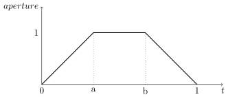
| Name | Type | Default |
|---|---|---|
clippingrange | double |
Distance of the near and far clipping planes from the camera. It’s defined by a list of exactly two values:
- Distance to the
nearclipping plane, in front of which scene objects are clipped. - Distance to the
farclipping plane, behind which scene objects are clipped.
orthographiccamera
This node defines an orthographic camera with a view direction towards the Z- axis. This camera has no specific attributes.
perspectivecamera
This node defines a perspective camera. The canonical camera is viewing in the direction of the Z- axis. The node is usually connected into a transform node for camera placement. It has the following attributes:
| Name | Type | Default |
|---|---|---|
fov | float |
The field of view angle, in degrees.
| Name | Type | Default |
|---|---|---|
depthoffield.enable | int | 0 |
Enables depth of field effect for this camera.
| Name | Type | Default |
|---|---|---|
depthoffield.fstop | double |
Relative aperture of the camera.
| Name | Type | Default |
|---|---|---|
depthoffield.focallength | double |
Vertical focal length, in scene units, of the camera lens.
| Name | Type | Default |
|---|---|---|
depthoffield.focallengthratio | double | 1 |
Ratio of vertical focal length to horizontal focal length. This is the squeeze ratio of an anamorphic lens.
| Name | Type | Default |
|---|---|---|
depthoffield.focaldistance | double |
Distance, in scene units, in front of the camera at which objects will be in focus.
| Name | Type | Default |
|---|---|---|
depthoffield.aperture.enable | int | 0 |
By default, the renderer simulates a circular aperture for depth of field. Enable this feature to simulate aperture “blades” as on a real camera. This feature affects the look in out-of-focus regions of the image.
| Name | Type | Default |
|---|---|---|
depthoffield.aperture.sides | int | 5 |
Number of sides of the camera’s aperture. The minimum number of sides is 3.
| Name | Type | Default |
|---|---|---|
depthoffield.aperture.angle | double | 0 |
A rotation angle (in degrees) to be applied to the camera’s aperture, in the image plane.
| Name | Type | Default |
|---|---|---|
unitlengthmillimeters | double |
Physical length, in millimeters, of one scene unit. Since NSI only uses virtual scene units, this has no effect on the rendered images. However, this value can be useful if the renderer has to communicate with other software or file formats using physical units. For example, the focal length of the camera, expressed in millimeters, would be the product depthoffield.focallength * unitlengthmillimeters.
fisheyecamera
Fish eye cameras are useful for a multitude of applications (e.g. virtual reality). This node accepts these attributes:
| Name | Type | Default |
|---|---|---|
fov | float |
Specifies the field of view for this camera node, in degrees.
| Name | Type | Default |
|---|---|---|
mapping | string | equidistant |
Defines one of the supported fisheye mapping functions:
equidistant— Maintains angular distances.equisolidangle— Every pixel in the image covers the same solid angle.orthographic— Maintains planar illuminance. This mapping is limited to a 180 field of view.stereographic— Maintains angles throughout the image. Note that stereographic mapping fails to work with field of views close to 360 degrees.
cylindricalcamera
This node specifies a cylindrical projection camera and has the following attributes:
| Name | Type | Default |
|---|---|---|
fov | float | 90 |
Specifies the vertical field of view, in degrees.
| Name | Type | Default |
|---|---|---|
horizontalfov | float | 360 |
Specifies the horizontal field of view, in degrees.
| Name | Type | Default |
|---|---|---|
eyeoffset | float |
This offset allows to render stereoscopic cylindrical images by specifying an eye offset.
sphericalcamera
This node defines a spherical projection camera. This camera has no specific attributes.
Lens Shaders
A lens shader is an ᴏsʟ network connected to a camera through the lensshader connection. Such shaders receive the position and the direction of each tracer ray and can either change or completely discard the traced ray. This allows to implement distortion maps and cut maps. The following shader variables are provided:
P— Contains ray’s origin.I— Contains ray’s direction. Setting this variable to zero instructs the renderer not to trace the corresponding ray sample.time— The time at which the ray is sampled.(u, v)— Coordinates, in screen space, of the ray being traced.
Script Objects
It is a design goal to provide an easy to use and flexible scripting language for ɴsɪ.
The Lua language has been selected for such a task because of its performance, lightness and features1. A flexible scripting interface greatly reduces the need to have API extensions.
For example, what is known as ‘conditional evaluation’ and ‘Ri filters’ in the RenderMan API are superseded by the scripting features of ɴsɪ.
[!NOTE] Although they go hand in hand, scripting objects are not to be confused with the Lua binding.
The binding allows for calling ɴsɪ functions in Lua while scripting objects allow for scene inspection and decision making in Lua. Script objects can make Lua binding calls to make modifications to the scene.
To be continued …
Footnotes
-
Lua is also portable and streamable. ↩
Rendering Guidelines
Basic Scene Anatomy
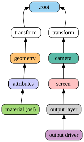
A minimal (and useful) ɴsɪ scene graph contains the three following components:
- Geometry linked to the
.rootnode, usually through a transform chain. - ᴏsʟ materials linked to scene geometry through an attributes node.
- At least one outputdriver → outputlayer → screen → camera →
.rootchain to describe a view and an output device.
The scene graph above shows a renderable scene with all the necessary elements. Note how the connections always lead to the .root node.
In this view, a node with no output connections is not relevant by definition and will be ignored.
[!CAUTION] For the scene to be visible, at least one of the materials has to be emissive.
A Word – or Two – About Attributes
Those familiar with the RenderMan standard will remember the various ways to attach information to elements of the scene (standard attributes, user attributes, primitive variables, construction parameters). E.g parameters passed to RenderMan Interface calls to build certain objects. For example, knot vectors passed to RiNuPatch().
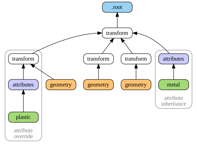
In ɴsɪ things are simpler and all attributes are set through the NSISetAttribute() mechanism. The only distinction is that some attributes are required (intrinsic attributes) and some are optional: a mesh node needs to have P and nvertices defined — otherwise the geometry is invalid.
[!NOTE] In this documentation, all intrinsic attributes are documented at the beginning of each section describing a particular node.
In ᴏsʟ shaders, attributes are accessed using the getattribute() function and this is the only way to access attributes in ɴsɪ. Having one way to set and to access attributes makes things simpler (a design goal) and allows for extra flexibility (another design goal). The figure above shows two features of attribute assignment in ɴsɪ:
Attribute inheritance
: Attributes attached at some parent (in this case, a metal material) affect geometry downstream.
Attribute override
: It is possible to override attributes for a specific geometry by attaching them to a transform node directly upstream (the plastic material overrides metal upstream).
Note that any non-intrinsic attribute can be inherited and overridden, including vertex attributes such as texture coordinates.
Instancing
Instancing in ɴsɪ is naturally performed by connecting a geometry to more than one transform (connecting a geometry node into a transform.objects attribute).
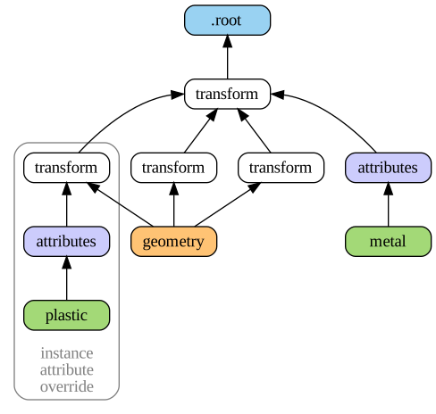
The above figure shows a simple scene with a geometry instanced three times. The scene also demonstrates how to override an attribute for one particular geometry instance, an operation very similar to what we have seen in the attributes section. Note that transforms can also be instanced and this allows for instances of instances using the same semantics.
Creating ᴏsʟ Networks
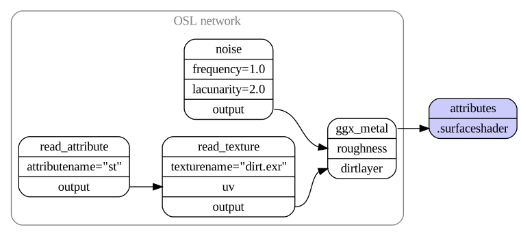
The semantics used to create ᴏsʟ networks are the same as for scene creation. Each shader node in the network corresponds to a shader node which must be created using NSICreate. Each shader node has implicit attributes corresponding to shader’s parameters and connection between said arguments is done using NSIConnect. Above diagram depicts a simple ᴏsʟ network connected to an attributes node.
Some observations:
- Both the source and destination attributes (passed to NSIConnect) must be present and map to valid and compatible shader parameters (Lines 21–23).
[!NOTE] There is an exception to this: any non-shader node can be connected to a string attribute of a shader node. This will result in the non-shader node’s handle being used as the string’s value.
This behavior is useful when the shader needs to refer to another node, in a ᴏsʟ call to
transform()orgetattribute(), for example.
- There is no symbolic linking between shader arguments and geometry attributes (a.k.a. primvars). One has to explicitly use the
getattribute()ᴏsʟ function to read attributes attached to geometry. In the example above, this is done in theread_attributenode (Lines 11–14). Also see the section on attributes.
Create "ggx_metal" "shader"
SetAttribute "ggx"
    "shaderfilename" "string" 1  ["ggx.oso"]

Create "noise" "shader"
SetAttribute "noise"
    "shaderfilename" "string" 1 ["simplenoise.oso"]
    "frequency" "float" 1 [1.0]
    "lacunarity" "float" 1 [2.0]

Create "read_attribute" "shader"
SetAttribute "read_attribute"
    "shaderfilename" "string" 1 ["read_attributes.oso"]
    "attributename" "string" 1 ["st"]

Create "read_texture" "shader"
SetAttribute "read_texture"
    "shaderfilename" "string" 1 ["read_texture.oso"]
    "texturename" "string" 1 ["dirt.exr"]

Connect "read_attribute" "output" "read_texture" "uv"
Connect "read_texture" "output" "ggx_metal" "dirtlayer"
Connect "noise" "output" "ggx_metal" "roughness"

# Connect the OSL network to an attribute node
Connect "ggx_metal" "Ci" "attr" "surfaceshader"
Lighting in the Nodal Scene Interface
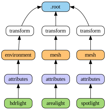
There are no special light source nodes in ɴsɪ (although the environment node, which defines a sphere of infinite radius, could be considered a light in practice).
Any scene geometry can become a light source if its surface shader produces an emission() closure. Some operations on light sources, such as light linking, are done using more general approaches.
Following is a quick summary on how to create different kinds of light in ɴsɪ.
Area Lights
Area lights are created by attaching an emissive surface material to geometry. Below is a simple ᴏsʟ shader for such lights (standard ᴏsʟ emitter).
// Copyright (c) 2009-2010 Sony Pictures Imageworks Inc., et al.  All Rights Reserved.
surface emitter     [[ string help = "Lambertian emitter material" ]]
(
    float power = 1 [[ string help = "Total power of the light" ]],
    color Cs = 1    [[ string help = "Base color" ]])
{
    // Because emission() expects a weight in radiance, we must convert by dividing
    // the power (in Watts) by the surface area and the factor of PI implied by
    // uniform emission over the hemisphere. N.B.: The total power is BEFORE Cs
    // filters the color!
    Ci = (power / (M_PI * surfacearea())) * Cs * emission();
}
Spot and Point Lights
Such lights are created using an epsilon sized geometry (a small disk, a particle, etc.) and optionally using extra arguments to the emission() closure.
surface spotlight(
    color i_color = color(1),
    float intenstity = 1,
    float coneAngle = 40,
    float dropoff = 0,
    float penumbraAngle = 0
) {
    color result = i_color * intenstity * M_PI;

    // Cone and penumbra
    float cosangle = dot(-normalize(I), normalize(N));
    float coneangle = radians(coneAngle);
    float penumbraangle = radians(penumbraAngle);

    float coslimit = cos(coneangle / 2);
    float cospen = cos((coneangle / 2) + penumbraangle);
    float low = min(cospen, coslimit);
    float high = max(cospen, coslimit);

    result *= smoothstep(low, high, cosangle);

    if (dropoff > 0) {
        result *= clamp(pow(cosangle, 1 + dropoff),0,1);
    }
    Ci = result / surfacearea() * emission();
}
Directional and HDR Lights
Directional lights are created by using the environment node and setting the angle attribute to 0. HDR lights are also created using the environment node, albeit with a 2π cone angle, and reading a high dynamic range texture in the attached surface shader. Other directional constructs, such as solar lights, can also be obtained using the environment node.
Since the environment node defines a sphere of infinite radius any connected ᴏsʟ shader must only rely on the I variable and disregard P, as is shown below.
shader hdrlight(
    string texturename = ""
) {
    vector wi = transform("world", I);

    float longitude = atan2(wi[0], wi[2]);
    float latitude = asin(wi[1]);

    float s = (longitude + M_PI) / M_2PI;
    float t = (latitude + M_PI_2) / M_PI;

    Ci = emission() * texture(texturename, s, t);
}
[!NOTE] Environment geometry is visible to camera rays by default so it will appear as a background in renders. To disable this simply switch off camera visibility on the associated attributes node.
Defining Output Drivers and Layers
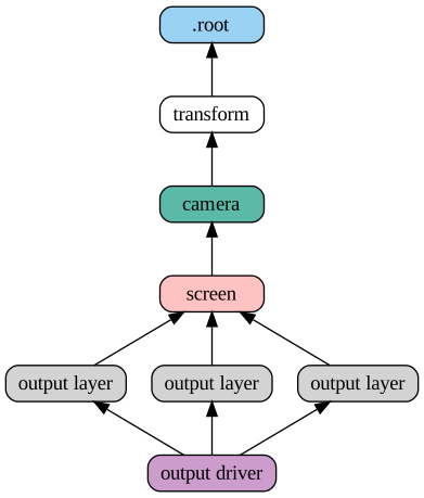
ɴsɪ allows for a very flexible image output model. All the following operations are possible:
- Defining many outputs in the same render (e.g. many EXR outputs)
- Defining many output layers per output (e.g. multi-layer EXRs)
- Rendering different scene views per output layer (e.g. one pass stereo render)
- Rendering images of different resolutions from the same camera (e.g. two viewports using the same camera, in an animation software)
The figure above depicts an ɴsɪ scene that creates one file with three layers. In this case, all layers are saved to the same file and the render is using one view. A more complex example is shown below: a left and a right camera are used to drive two file outputs, each having two layers (Ci and Diffuse colors).
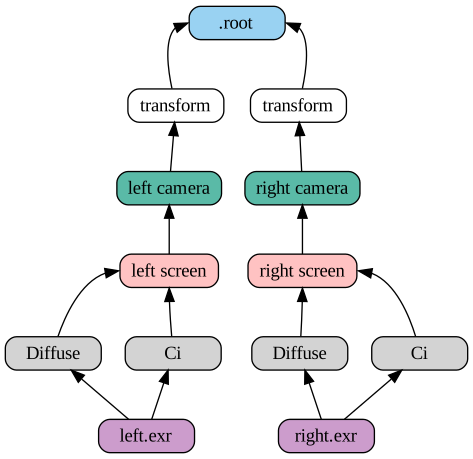
Light Layers
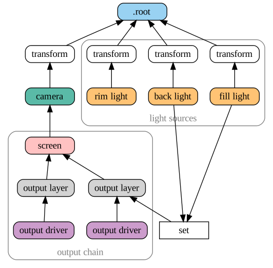
The ability to render a certain set of lights per output layer has a formal workflow in ɴsɪ. One can use three methods to define the lights used by a given output layer:
- Connect the geometry defining lights directly to the
outputlayer.lightsetattribute - Create a set of lights using the
setnode and connect it intooutputlayer.lightset - A combination of both 1 and 2
The diagram above shows a scene using method 2 to create an output layer containing only illumination from two lights of the scene. Note that if there are no lights or light sets connected to the lightset attribute then all lights are rendered. The final output pixels contain the illumination from the considered lights on the specific surface variable specified in outputlayer.variablename ().
Inter-Object Visibility
Some common rendering features are difficult to achieve using attributes and hierarchical tree structures. One such example is inter-object visibility in a 3D scene. A special case of this feature is light linking which allows the artist to select which objects a particular light illuminates, or not. Another classical example is a scene in which a ghost character is invisible to camera rays but visible in a mirror.
In ɴsɪ such visibility relationships are implemented using cross-hierarchy connection between one object and another. In the case of the mirror scene, one would first tag the character invisible using the visibility attribute and then connect the attribute node of the receiving object (mirror) to the visibility attribute of the source object (ghost) to override its visibility status. Essentially, this “injects” a new value for the ghost visibility for rays coming from the mirror.

Above figure shows a scenario where both hierarchy attribute overrides and inter-object visibility are applied:
-
The ghost transform has a visibility attribute set to 0 which makes the ghost invisible to all ray types
-
The hat of the ghost has its own attribute with a visibility set to 1 which makes it visible to all ray types
-
The mirror object has its own attributes node that is used to override the visibility of the ghost as seen from the mirror. The nsi stream code to achieve that would look like this:
Connect "mirror_attribute" "" "ghost_attributes" "visibility"
    "value" "int" 1 [1]
    "priority" "int" 1 [2]
Here, a priority of
2has been set on the connection for documenting purposes, but it could have been omitted since connections always override regular attributes of equivalent priority.
Footnotes
Cookbook
The Nodal Scene Interface (NSI) is a simple yet expressive API to describe a scene to a renderer. From geometry declaration, to instancing, to attribute inheritance and shader assignments, everything fits in 12 API calls. The following recipes demonstrate how to achieve most common manipulations.
Geometry Creation
Creating geometry nodes is simple. The content of each node is filled using the NSISetAttribute call.
## Polygonal meshes can be created minimally by specifying "P".
## NSI's C++ API provides an easy interface to pass parameters to all NSI
## API calls through the Args class.

Create "simple polygon" "mesh"
SetAttribute "simple polygon"
    "P" "point" 1 [ -1  1  0   1  1  0   1 -1  0   -1 -1  0 ]
Geometry Creation in C++
/*
    Polygonal meshes can be created minimally by specifying "P".
    NSI's C++ API provides an easy interface to pass parameters
    to all NSI API calls through the Args class.
*/
const char *k_poly_handle = "simple polygon"; /* avoids typos */

nsi.Create( k_poly_handle, "mesh" );

NSI::ArgumentList mesh_args;
float points[3*4] = { -1, 1, 0,  1, 1, 0, 1, -1, 0, -1, -1, 0 };
mesh_args.Add(
    NSI::Argument::New( "P" )
        ->SetType( NSITypePoint )
        ->SetCount( 4 )
        ->SetValuePointer( points ) );
nsi.SetAttribute( k_poly_handle, mesh_args );
Specifying normals and other texture coordinates follows the same logic. Constant attributes can be declared in a concise form too:
SetAttribute "simple polygon"
    "subdivision.scheme" "string" 1 ["catmull-clark"]
Adding constant attributes in C++
/** Turn our mesh into a subdivision surface */
nsi.SetAttribute( k_poly_handle,
    NSI::CStringPArg("subdivision.scheme", "catmull-clark") );
Transforming Geometry
In NSI, a geometry is rendered only if connected to the scene’s root (which has the special handle “.root”). It is possible to directly connect a geometry node (such as the simple polygon above) to scene’s root but it wouldn’t be very useful. To place/instance a geometry anywhere in the 3D world a transform node is used as in the code snippet below.
Create "my translation" "transform"
Connect "translation"  "" ".root" "objects"
Connect "simple polygon" "" "translation" "objects" );

# Transalte 1 unit in Y
SetAttribute "my translation"
    "transformationmatrix" "doublematrix" 1 [
    1 0 0 0
    0 1 0 0
    0 0 1 0
    0 1 0 1]
Adding constant attributes in C++
const char *k_instance1 = "my translation";

nsi.Create( k_instance1, "transform" );
nsi.Connect( k_instance1, "", NSI_SCENE_ROOT, "objects" );
nsi.Connect( k_poly_handle, "", k_instance1, "objects" );

/*
    Matrices in NSI are in double format to allow for greater
    range and precision.
*/
double trs[16] =
{
    1., 0., 0., 0.,
    0., 1., 0., 0.,
    0., 0., 1., 0.,
    0., 1., 0., 1. /* transalte 1 unit in Y */
};

nsi.SetAttribute( k_instance1,
    NSI::DoubleMatrixArg("transformationmatrix", trs) );
Instancing is as simple as connecting a geometry to different attributes. Instances of instances do work as expected too.
const char *k_instance2 = "another translation";
trs[13] += 1.0; /* translate in Y+ */

nsi.Create( k_instance2, "transform" );
nsi.Connect( k_poly_handle, "", k_instance2, "objects" );
nsi.Connect( k_instance2, "", NSI_SCENE_ROOT, "objects" );

/* We know have two instances of the same polygon in the scene */
Implementer FAQ
Questions an implementer of ɴsɪ runs into when the specification is silent, or when it says one thing and 3Delight does another. Each answer gives the rule, what was observed, and what an implementation should do.
Unless stated otherwise, the observations come from 3Delight 2.9.207. Each was rendered, not read from documentation: a small scene, rendered twice with one change between the renders.
Attributes and Priority
Two attributes nodes on one node set the same attribute at the same priority. Which one applies?
Answer. The node connected first applies. The order of the NSIConnect() calls is part of the scene.
Observed. A plane with two sibling attributes nodes, one with visibility.camera 0 and one with 1. The plane is visible when the visible node is connected first, and hidden when the hidden node is connected first. Handle names and creation order run against the connection order, so they do not decide. The same rule applies to shaders: with a red and a green shader on two sibling attributes nodes, the plane takes the colour of the node connected first. 3Delight prints no warning in either case.
For implementers. Resolve the tie in connection order. Also warn, and list the definitions that were dropped: a scene whose look depends on call order is almost never intentional. The author can remove the ambiguity with ATTR.priority, or with a priority on the shader connection. See the attributes node.
Does a priority on a geometryattributes connection change which attributes node wins?
Answer. No. The priority of a connection has an effect only on shader connections, such as surfaceshader. To rank an attributes node, set ATTR.priority on that node.
Observed. The specification says both things. The NSIConnect() argument table says priority “indicates in which order the nodes should be considered”. The attributes node page says connections can be assigned priorities “(for shaders, essentially)”. 3Delight follows the second sentence:
Connect "near" "" "mesh" "geometryattributes"
Connect "far" "" "xf" "geometryattributes" "priority" "int" 1 [ 10 ]
SetAttribute "near" "visibility" "int" 1 [ 0 ]
SetAttribute "far" "visibility" "int" 1 [ 1 ]
The mesh stays hidden: near wins, and the connection priority has no effect. Replace the connection argument with "visibility.priority" "int" 1 [ 10 ] on far and the mesh is visible. renderdl -cat echoes the connection argument back, so the renderer parses it and then ignores it.
For implementers. Read the connection priority for the three shader slots. Ignore it on geometryattributes.
An attributes node sets ATTR.priority but not ATTR. Does it define anything?
Answer. Yes. It defines ATTR at its default value, and that definition ranks with the given priority like any other.
Observed. An attributes node with only visibility.priority makes the geometry visible over a farther visibility 0, at priority 10 and also at priority 0. The same node two levels up, at priority 10, also wins over a visibility 0 on the node attached to the geometry itself. So it does not win only because it is nearer. A node with no attributes defines nothing.
For implementers. Treat a lone ATTR.priority as a definition of ATTR with its default value.
Which types does ATTR.priority accept?
Answer. Exactly one int. 3Delight ignores the priority when it has any other type or count, and then the definition ranks at priority 0.
Observed. An int64 priority of 10 loses to a nearer definition with no priority. A priority written "int" 2 [ 10 10 ] or "int[2]" 1 [ 10 10 ] is also ignored.
For implementers. Accept a single int. Do not take the first value of a longer array, and do not convert an int64.
Which wins: a far visibility.camera or a nearer visibility?
Answer. At equal priority, the far visibility.camera. The more specific attribute wins before proximity is compared.
For implementers. Rank the candidates by priority first, then by specificity (per-ray before visibility), then by distance from the geometry, then by connection order.
Is an attribute value read strictly by its type?
Answer. No. 3Delight reads a value much more loosely than a priority. On visibility, a float 0.4 is visible and a float 0 is hidden, an int64 0 hides, and a string reads as true. A value of the wrong type is still a definition: it wins its ranking, so the renderer does not look further up the path.
For implementers. Do not treat a value of an unexpected type as “not defined”. That shows the object where the renderer hides it, or the reverse.
Are set nodes a source of attributes?
Answer. Yes, for geometryattributes and for shaderattributes, although the gathering rule names only geometry and transform nodes. Only direct membership counts.
Observed. For each node on the path from the geometry to the root, the order is:
- The node’s own attributes nodes.
- The attributes nodes on the sets the node is directly a member of, in the order of the memberships.
- The next node up the path.
A set inside another set contributes nothing. A set that holds two nodes of the path counts once, at the nearer node. ATTR.priority still ranks above all of this.
For implementers. Gather set containers at each level, with direct membership only.
A geometry has two parents. Which attributes apply?
Answer. Each path to the root applies its own attributes. Connecting a geometry to two transforms draws it twice, and each copy gathers attributes along its own path.
Observed. One parent with visibility 1 and one with visibility 0 draws one copy, not two and not none.
For implementers. Resolve attributes per path, not per geometry.
Types and Motion
What happens to motion samples when one sample has the wrong type?
Answer. The wrong sample unsets the attribute and discards every sample before it. Only the samples set after it remain.
Observed. A good doublematrix at t=0, a float at t=1 and a good doublematrix at t=2 draw a static object at the t=2 matrix. 3Delight warns E6007. Without the float, the object moves across the frame.
For implementers. Do not skip the bad sample and keep the others. That shows motion blur that the renderer does not draw.
Is "double" 16 [...] a matrix?
Answer. No. transformationmatrix must be a doublematrix. With sixteen double values, 3Delight warns E6007 and draws the node at the identity transform. In a stream, the type name for an integer is int: "integer" is rejected with E1000 and the call is skipped.
Can a Lua script pass an int64 or a double?
Answer. Not in 3Delight 2.9.210. nsi.TypeInt64, nsi.TypeDouble and nsi.TypePointer are nil, so an argument that names one of them has no type. The renderer then infers a type and changes the value without an error.
Observed. With renderdl -lua -cat, data=9007199254740993, type=nsi.TypeInt64 is written as "int" 1 1, and data=0.1, type=nsi.TypeDouble is written as a float.
For implementers. Define all type constants in the Lua binding, including the 64-bit ones. A value that cannot be represented should be an error, not a silent conversion. See the Lua API.
The Stream Format
Is the stream line-based?
Answer. No. The stream is a sequence of tokens. A complete scene on one line parses. A parameter list ends at the next bare token that is a statement keyword. Parameter names are always quoted, so this is not ambiguous. Whitespace runs are free, and # starts a comment that ends at the end of the line.
Observed. renderdl -cat reads Create "a" "transform" Create "b" "mesh" SetAttribute "b" "fov" "float" 1 45 as separate statements.
Which escapes does a string accept?
Answer. 3Delight writes \", \\, \t and \n by name, each other byte below 0x20 as three octal digits, such as \001, and each byte at or above 0x7f unchanged. It reads octal escapes of one to three digits. There is no \x.
For implementers. A string is a sequence of bytes, not UTF-8 text. A file name in Latin-1 is valid, so do not reject it.
Does a reader expand ${VAR} in a string?
Answer. No. The value stays as written in the stream. 3Delight expands the reference when it uses the value, for example when it opens a file. Every variable expands, not only variables whose name starts with NSI_PATH_. That prefix only controls which paths streampathreplacement writes as references.
Observed. renderdl -cat echoes ${NSI_PATH_TEST}/out.exr unchanged. A render with that imagefilename writes to the expanded path.
For implementers. Keep the reference in a stream that you read and write again. Expand it where you open the file.
Why does a stream I wrote not start with text?
Answer. With the autonsi format, which is the default, 3Delight writes binarynsi unless the file name ends in .nsia. The binary encoding is not documented. Its files start with the bytes cc 00. To get text, name the file .nsia or convert the file with renderdl -cat.
Threads
Can I make calls on one context from many threads?
Answer. 3Delight accepts calls from several threads. But 3Delight 2.9 runs the calls on one context one at a time, so more threads do not make them faster.
Observed. 20,000 SetAttribute calls on existing meshes take 11.8 ms from one thread and 21.4 ms from sixteen threads. 20,000 Create calls take 11.4 ms and 10.8 ms.
For implementers. To load a scene faster, do the parsing on other threads and send the calls in order. If calls on your implementation can run concurrently, the order still matters: Create before use, and Connect calls into one attribute in stream order (see the first question).
Implementations
ɴsɪ is an interface, and more than one renderer implements it. This chapter lists, for each implementation, where it goes beyond the specification and where it falls short of it.
Each page has the same sections:
- Extensions: what the implementation accepts or provides beyond the specification.
- Limitations: parts of the specification it does not implement, or implements differently.
- Behavior the specification leaves open: how it resolves a case the specification does not decide. The Implementer FAQ states these as questions.
An item is listed only when it was observed – rendered, or read back from the implementation – not when it was only read in documentation. Each page names the version it was observed with.
3Delight
3Delight by Illumination Research is the reference implementation of ɴsɪ. The observations on this page were made with 3Delight 2.9.210 unless a version is named.
Extensions
- ᴏsʟ extensions. 3Delight resolves intersecting subsurface-scattering volumes with intersection priorities and merge sets. See ᴏsʟ Extensions.
- A binary stream format.
streamformatbinarynsiwrites an undocumented binary encoding.autonsi, which is the behavior for astreamfilenamethat does not end in.nsia, selects it. A binary stream starts with the bytescc 00.renderdl -catconverts it to text. - Lua scenes.
NSIEvaluatewithtypeluaruns a script with annsitable. See the Lua API and its limitations below. - Display drivers. An output driver’s
drivernameselects an ndspy display driver. 3Delight looks for<drivername>.dpyin the working directory, then in$DELIGHT/displaysand$DELIGHT/lib. No environment variable extends that path. A built-in driver name, such aspng, cannot be replaced by a file of the same name. - Cryptomatte built-ins. With
cryptomatte.enableat its default of 1, the built-in variablesid.geometry,id.scenepath,id.surfaceshaderandid.assetare written in Cryptomatte format. - Tools.
renderdlrenders a stream or a Lua script.renderdl -catwrites a stream back as text, andrenderdl -lua -catruns a Lua script and writes the calls it makes as a stream.
Limitations
- Lua cannot pass 64-bit values.
nsi.TypeInt64,nsi.TypeDoubleandnsi.TypePointerarenil. A value that names one of them is re-typed without an error: anint64becomes theint1, adoublebecomes afloat. See the FAQ. - A connection
priorityongeometryattributeshas no effect. Only apriorityon a shader connection, such assurfaceshader, ranks it. UseATTR.priorityon the attributes node instead. See the FAQ. - Calls on one context run one at a time. Several threads may call into one context, but they are serialized: 20,000
SetAttributecalls take 11.8 ms from one thread and 21.4 ms from sixteen. hpointneeds 2.9.210. Anurbssurface’sPwmust have the typehpoint. The same data as flatfloats is rejected (E6007), and the surface is then dropped (E6020). 3Delight 2.9.208 has neither the type nor the node.- Displacement needs
displacementbound. Adisplacementshaderhas no effect unless the attributes also setdisplacementbound, afloat: how far, at most, the displacement moves the surface. The manual does not mention it. The library also knows adisplacementboundspace, whose behavior is unverified. See the attributes node. - Any
basisoutside the three real values warns and falls back. Acurvesnode whosebasisis not"b-spline","catmull-rom"or"linear"warnsE6036 unsupported valueand falls back to the default,catmull-rom– confirmed for"hobby","bezier"and a nonsense string alike, with no special case for any particular name.
Behavior the Specification Leaves Open
- Equal-priority definitions resolve in connection order. When two attributes nodes on one node define the same attribute at the same priority, the one connected first applies, for plain attributes and for shaders. 3Delight prints no warning about the definitions it drops. See the attributes node.
- A lone
ATTR.priorityis a definition ofATTRat its default value. The priority must be exactly oneint; any other type or count is ignored. - Specificity ranks before proximity. At equal priority, a far
visibility.camerawins over a nearervisibility. - Values are read loosely. On
visibility, afloat0.4 is visible, anint640 hides, and astringreads as true. A value of the wrong type is still a definition. setnodes are attribute sources, forgeometryattributesandshaderattributes, with direct membership only.- A wrong-typed motion sample unsets the attribute and discards every sample before it (
E6007). ${VAR}in a string value expands at use, for any variable, when the value is used – for example when a file is opened. A stream reader keeps it as written.- The stream reader is lenient about type spellings.
"i point"reads aspoint.
Setup
- The library is
lib3delightin$DELIGHT/lib. Therenderdltool is in$DELIGHT/bin. - Without a license, 3Delight renders with a watermark in the image background. The license server (
licserver) must be running to use a node-locked license.
OSL Extensions in 3Delight
Subsurface Scattering Inside Intersecting Volumes
Subsurface scattering (SSS) is accessible in 3Delight through the ᴏsʟ subsurface() closure.
It simulates the scattering of light inside a volume bounded by a closed surface.
A complication that often arises when using this feature is the problem of intersecting SSS volumes.
This results in a third volume, also bounded by a composite closed surface.
3Delight handles overlapping SSS volumes that don’t have the same properties by mixing them together, thus creating a hybrid material inside the intersection.
For this to work properly, the ᴏsʟ subsurface() closure must be used on both entry and exit of the volume. As a consequence, it shouldn’t depend on the orientation of the bounding surface normal.
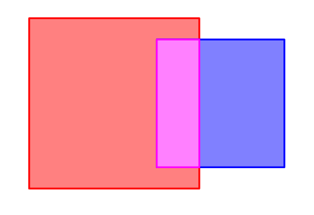
Intersection Priorities
However, this behavior can be changed by assigning priorities to SSS shaders through the optional intersectionpriority parameter of the subsurface() closure.
Inside the intersection, the SSS shader with the highest intersection priorities will be used exclusively.
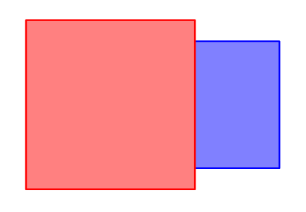
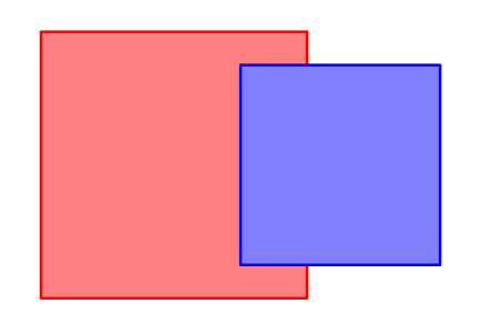
This tends to be useful when the intersection is not accidental, but rather the result of a decision made when defining the scene geometry. For example, in a model of a mouth a set of teeth can be designed to penetrate the geometry of the gums. This avoids modelling a small “pocket” on the gums around each tooth. In that case, the teeth should be assigned a higher priority than the gums in order for their roots to use only the tooth shader.
The intersectionpriority parameter is an integer between -60 and 60.
Its default value is 0.
Merge Sets
Even when overlapping SSS objects use the same shader, 3Delight still treats the intersection as a separate volume with its own surface. This is often not the desired effect. The geometry of the intersecting objects is still intact, so it hinders the propagation of light inside the volumes. The result is darker or brighter areas on the surface along the boundary.
This can be fixed by assigning a Merge Set name to each SSS material through the optional mergeset parameter of the subsurface() closure.
SSS volumes within the same Merge Set will be considered as a single volume, without internal divisions.
This tends to be useful when a complex object is made up of multiple pieces of geometry that overlap in order to appear as a single object.
MoonRay
MoonRay is DreamWorks’ open-source production renderer. It has no ɴsɪ interface of its own. The nsi-moonray backend translates ɴsɪ calls into a MoonRay scene and ships as a library that exports the ɴsɪ C API. The items on this page are recorded in that project’s specifications and were observed with MoonRay commit eef67ae, with 3Delight 2.9.209 as the reference for comparisons.
Extensions
- ᴏsʟ shader networks run in MoonRay. An ɴsɪ shader network becomes one ᴏsʟ shader group, evaluated by three MoonRay plug-ins:
Oslfor surfaces,OslDisplacementandOslMap. The backend must be built with ᴏsʟ available; without it, each shader is replaced by aUsdPreviewSurfacewith parameters read from 3Delight’s shaders, and displacement is dropped with a report. - Every emitter runs its actual shader, not a name lookup. ɴsɪ has no light nodes: a light is geometry whose surface shader produces an
emission()closure. Every such emitter becomes a MoonRayMeshLight, lit by anOslMaprunning that same network – colour, intensity, and how both vary across the surface, come from the closure itself, sampled per point. Shader-name recognition (areaLight,pointLight,spotLight,distantLight) is a fallback only, for a build with no ᴏsʟ or a shader with no compiled.osobehind it; then MoonRay supplies the photometry and the light is in the right place with the wrong look. - 3Delight’s ᴏsʟ closures are understood.
layer_closures,outputvariableandoutputconstantare registered, andmicrofacet’srealeta/complexetabuild a conductor. The MaterialX closures (dielectric_bsdf,conductor_bsdf,generalized_schlick_bsdf,sheen_bsdf,subsurface_bssrdf,uniform_edf,layerand others) are mapped too. - Per-lobe AOVs. An output variable that names a lobe becomes a MoonRay light-path expression. 3Delight’s variable names are translated, for example
reflectiontospecularandincandescencetoemission. - Output drivers without ndspy. An output driver named
ferris_f32(or_u32,_i32,_u16,_i16,_u8,_i8) calls Rust closures passed ascallback.open,callback.writeandcallback.finish. - Scene export.
$NSI_MOONRAY_SCENEwrites the translated scene as MoonRay.rdla. Themnrycommand renders, converts and watches.nsifiles. - A geometry shared under several transforms keeps every material. ɴsɪ’s lightweight instancing – connecting one node to several transforms, each with its own bound material – is one shared object in the interface, and
RdlMeshGeometrycannot do that natively: one object, one transform, one material. The backend expands the shared node into oneRdlMeshGeometryper placement at the translator boundary instead of dropping every material but one. Nothing in the ɴsɪ scene is lost, only duplicated internally.
Limitations
- At most two motion samples per attribute, on one shutter for the whole scene. More samples are reported, not rendered, and each object’s motion is resampled onto the scene’s shutter.
- Moving instances translate only. Rotation or scale of an
instancesnode across the shutter is reported, not rendered. suspendandresumeare not supported. Restarting a MoonRay frame loses the samples taken so far.vdbparticlesis not supported. MoonRay has no geometry that reads a point-data grid.- A scalar OpenVDB emission grid is refused, and the volume with it.
MoonRay’sVdbGeometryreads only an RGB emission grid. (volumeshaderitself is used: a bound ᴏsʟ volume closure crosses as anOslVolumeand runs.) - An
environmentnode’s shader does not run, since MoonRay’sEnvLightis a light class, not a shader. Colour, intensity, exposure and a texture path cross; gradients, mappings and every other per-component contribution the shader computes do not. - ᴏsʟ details that are dropped: colored transparency becomes one scalar presence; MaterialX tints become their luminance;
occlusion()and themicrofacetkeywordsgamma,thinfilmthickness,thinfilmetaandmediumetaare ignored with a warning; scopedgetattribute("scope", "name", ...)is not answered. - An emissive mesh cannot also have a non-emissive material, such as glowing metal.
- One renderer per process. A second concurrent render is refused; use a second process.
- An orthographic camera renders empty through the in-process progressive path. It renders through the spawned
moonrayprogram. - Output-driver callbacks need one shared build. Rust closures work only when the application and the backend use the same
nsi-ffi-wrap.
Behavior That Differs From 3Delight
- Pixels are pulled, not pushed. MoonRay renders progressively but does not deliver buckets. The backend polls it and sends each changed rectangle to the output driver.
- Channels are named after the layer. The beauty output has the channels
Ci.R,Ci.GandCi.B, without alpha, not RGBA. - A plain
meshis not subdivided. MoonRay’s mesh subdivides by default; the backend turns that off unlesssubdivision.schemeis set. - ᴏsʟ
+adds closures. Onlylayer()andlayer_closureslayer them with attenuation. - A disconnected object is switched off, not removed, in an interactive session.
- A scene without a camera gets a default one, and geometry without a shader gets a default material.
fovis vertical, matching 3Delight’s framing to within a pixel.
Known MoonRay Bugs
Found while writing the backend; none is filed upstream yet.
- A scene without a camera crashes MoonRay. The backend adds a default camera.
- Changing visibility re-tessellates the geometry instead of only rebuilding the acceleration structure, so hiding and showing is not cheap in an interactive session.
- A mesh light needs a material from the separate
moonshine_dwapackage; a MoonRay-only build fails. The backend provides a stand-in. - A material without a vectorized shading function renders black in MoonRay’s default mode. The backend forces scalar mode.
- A mesh light with a map shader crashes when its geometry is in no geometry set. The backend adds one.
Setup
- The library is
libnsi_moonray.so(.dylibon macOS,nsi_moonray.dllon Windows). It exports the ɴsɪ C API. - MoonRay’s plug-in directory is found without being named: beside the running binary first, then the platform’s own per-user and system-wide install locations.
$NSI_MOONRAY_DSOoverrides that search and is never second-guessed. If nothing is found anywhere, the in-process path reports every directory it tried and falls back to spawning themoonrayprogram rather than rendering silently empty. - The backend links MoonRay when built with the
rdl2feature. Otherwise it writes.rdlaand runs themoonrayprogram. - MoonRay is licensed under Apache-2.0; nsi-moonray under MIT, Apache-2.0 or Zlib.
NURBS: Draft Design
This page is the draft of a future version of the nurbs node: a NURBS surface patch – a tensor-product spline defined by a grid of control points, two knot vectors, and an order in each parametric direction.
3Delight 2.9.210 implements the
nurbsnode with the legacy attribute names; the reference page documents it. This draft was written before that release. It uses the new naming convention and proposes changes beyond the renames: consolidated trim-curve control points, per-loop holes, and stitching. Where this draft and the shipped node differ, the reference page is correct for 3Delight today:
- The shipped
Pwhas the typehpoint, notweighted-point.- The shipped node has no loop count. The number of
trimcurves.ncurvesvalues is the number of loops.- The shipped
trimcurves.insideis one optional value, and 1 keeps the surface inside a loop. The draft’strim-curves.holehas one value per loop, and 1 removes it.
It has the following required attributes:
| Name | Type | Default |
|---|---|---|
u.count | int |
Control-point count along u. Total control-point count is u.count * v.count. Should be at least u.order; if smaller, the surface is rendered with order equal to u.count.
| Name | Type | Default |
|---|---|---|
v.count | int |
Control-point count along v. Same constraint as u.count relative to v.order.
| Name | Type | Default |
|---|---|---|
u.order | int |
Order along u: degree + 1, so 2 is linear, 3 quadratic, 4 cubic. Must be at least 2. May differ from v.order.
| Name | Type | Default |
|---|---|---|
v.order | int |
Order along v. See u.order.
| Name | Type | Default |
|---|---|---|
u.knot | float |
Knot vector along u. Length must equal u.count + u.order. Values must be non-decreasing.
| Name | Type | Default |
|---|---|---|
v.knot | float |
Knot vector along v. Length must equal v.count + v.order. Values must be non-decreasing.
The surface’s active parameter range can be restricted with the optional u.min/u.max/v.min/v.max attributes. Unlike other geometric primitives, NURBS surfaces do not assume [0, 1] parameter ranges – by default, the active range is the full extent of the corresponding knot vector.
| Name | Type | Default |
|---|---|---|
u.min | float |
Lower bound of the active range along u. Must be less than u.max and at least the (u.order - 1)-th value of u.knot.
| Name | Type | Default |
|---|---|---|
u.max | float |
Upper bound of the active range along u. Must be greater than u.min and at most the u.count-th value of u.knot.
| Name | Type | Default |
|---|---|---|
v.min | float |
Lower bound of the active range along v. Must be less than v.max and at least the (v.order - 1)-th value of v.knot.
| Name | Type | Default |
|---|---|---|
v.max | float |
Upper bound of the active range along v. Must be greater than v.min and at most the v.count-th value of v.knot.
One of position or position-weighted must be supplied to provide the control points. position defines a polynomial surface; position-weighted defines a rational one.
| Name | Type | Default |
|---|---|---|
position | point |
The u.count * v.count control points (xyz), stored row-major: position[i * u.count + j] is the point at row i, column j.
| Name | Type | Default |
|---|---|---|
position-weighted | weighted-point |
Rational alternative to position: each control point is a weighted (homogeneous) point (wx, wy, wz, w), enabling rational NURBS. Same ordering as position. The weighted-point type is a draft addition – see Geometry in the Type System.
Trim Curves
How trim data is packaged – inline attributes as specified here, or dedicated nodes – is an open design question. See Trim Curves: API Alternatives for the alternatives under discussion; this page describes Option 1.
Trim curves carve a region out of the surface’s parameter domain. They are NURBS curves in the surface’s (u, v) parameter space – rational trim curves use homogeneous (u, v, w) control points, where the actual (u, v) of a control point is (u/w, v/w). Curves are organised into loops: within a loop they connect head-to-tail. Each loop must be explicitly closed – the last point of the last curve must coincide with the first point of the first curve.
The trim-curves.* attributes below are all-or-nothing: supply the full set or omit it entirely, with two exceptions. Supply exactly one of trim-curves.position and trim-curves.position-weighted, never both. And the stitching attributes trim-curves.edge-id/trim-curves.edge-orientation are optional – see Stitching.
| Name | Type | Default |
|---|---|---|
trim-curves.loop-count | int |
The number of trim loops.
| Name | Type | Default |
|---|---|---|
trim-curves.curve-count | int |
The number of curves in each loop. One value per loop.
| Name | Type | Default |
|---|---|---|
trim-curves.point-count | int |
The control-point count of each curve. One value per curve.
| Name | Type | Default |
|---|---|---|
trim-curves.order | int |
The order of each curve. One value per curve.
| Name | Type | Default |
|---|---|---|
trim-curves.knot | float |
The concatenated knot vectors for all curves. The total length is the sum over curves of point-count[i] + order[i].
| Name | Type | Default |
|---|---|---|
trim-curves.min | float |
The parametric start of each curve. One value per curve.
| Name | Type | Default |
|---|---|---|
trim-curves.max | float |
The parametric end of each curve. One value per curve.
| Name | Type | Default |
|---|---|---|
trim-curves.position | float[2] |
The concatenated control points of all curves as non-rational (u, v) pairs. The total length is the sum over curves of point-count[i].
| Name | Type | Default |
|---|---|---|
trim-curves.position-weighted | float[3] |
Rational alternative to trim-curves.position: the concatenated control points of all curves as homogeneous (u, v, w) triples. Same ordering and total length as trim-curves.position. These are deliberately plain float tuples, not point-typed data – parameter-space coordinates must never transform; see Geometry in the Type System.
| Name | Type | Default |
|---|---|---|
trim-curves.hole | int |
Whether each loop is a hole. One value per loop. A value of 0 keeps the surface inside the loop; a value of 1 marks the loop as a hole – the surface inside it is removed. Loops may nest, alternating: an island inside a hole is again 0.
Stitching
The shared-boundary design owns the common identity model, alternatives, and examples for NURBS, polygon, and subdivision surfaces. Its recommendation is one weld namespace node connected to every participating geometry node. One namespace can contain all joins in a solid.
The attributes below are a compact shorthand for one-segment boundary uses in that namespace. They are proposed additions, not shipped attributes. A surface supplies either these arrays or the general weld.* use table, never both.
A boundary use can also contain several segments. For example, five trim curves can jointly meet one subdivision boundary. That case uses the general table’s trim-loop selector or an explicit ordered chain; the per-curve shorthand cannot express that grouping.
The declaration asks the renderer to preserve the join through tessellation and displacement. It does not prescribe an algorithm. A renderer that ignores the declaration cannot guarantee the requested join.
Trim-Curve Edges
Both attributes below, when supplied, must be supplied together, with one value per curve (aligned with trim-curves.point-count, trim-curves.order, etc.).
| Name | Type | Default |
|---|---|---|
trim-curves.edge-id | int | -1 |
The edge identity of each curve. One value per curve. Each non-negative entry declares one complete boundary use. Uses with the same ID and connected weld node belong together, including uses on other geometry types. A value of -1 declares no use. Non-negative IDs require a weld connection; IDs are not scene-global.
| Name | Type | Default |
|---|---|---|
trim-curves.edge-orientation | int | 0 |
The traversal direction of each curve relative to its edge’s reference direction. One value per curve. A value of 0 means the curve, traversed from its parametric start to its end, follows the edge’s reference direction; 1 means it opposes it. This value becomes weld.reverse in the general table. After reversal, all uses follow the same reference traversal and share their start within tolerance, including closed boundaries. Native face-boundary orientation is separate. Equal parameter values still need not identify equal positions.
Natural Boundaries
In untrimmed patch networks – and on trimmed faces whose outer boundary is the natural parameter domain, such as a face carrying only hole loops – the welded edge is a whole side of the active domain rectangle [u.min, u.max] x [v.min, v.max]. Forcing such faces through the trimming machinery just to transport edge identities would be wasteful, so these welds are declared directly, per side.
| Name | Type | Default |
|---|---|---|
stitch.edge-id | int[4] | -1 |
The edge identities of the four sides of the active domain rectangle, in the order u = u.min, u = u.max, v = v.min, v = v.max. Values share the identifier space and semantics of trim-curves.edge-id: boundaries with equal non-negative values are stitched, -1 means no identity.
| Name | Type | Default |
|---|---|---|
stitch.edge-orientation | int[4] | 0 |
The traversal direction of each side relative to the shared reference traversal, in the same side order. A side’s native direction is increasing v for the two u-sides and increasing u for the two v-sides. A value of 1 reverses that native direction; 0 keeps it. The resulting traversal must agree with the other uses, including its start.
This shorthand selects a whole side, so that entire side must bound the retained region. Partly retained sides require explicit ranges in the general table. If a trim curve and a domain side describe the same boundary portion, only one selector declares that use.
A closed surface that is represented as a single patch split at a seam – a cylinder or torus, say – welds to itself by giving the two seam sides the same identity, e.g. equal values for the u = u.min and u = u.max entries of one node.
The per-side shorthand selects whole sides only. Partial sides and T-junctions use local ranges in the general boundary-use table.
Shared Semantics
The shared-boundary design defines identity scope, boundary chains, self-seams, and non-manifold joins. Natural-side and trim-curve shorthand entries follow those same rules. The exporter guarantees that counterpart chains describe the same spatial boundary within the source model’s tolerance. After reversal, starts, ends, and traversal directions agree. Segment counts and parameterizations can differ. Belonging does not ask the renderer to join unrelated geometry.
Each trim curve is a complete use in this shorthand. Five curves with one repeated ID are five uses, not one chain. Selecting the whole loop in the general table expresses a single use made from all five curves.
A trim-boundary use belongs to the retained surface adjacent to that loop. A hole therefore joins its surrounding surface, not the removed interior. Reversal changes correspondence direction, not the retained region. The retained-region rules apply to both shorthand and general declarations.
An optional 3D edge representation is a separate geometry extension. It is not required by these declarations.
Node Types: Naming and Granularity
The naming convention renames attributes consistently, but it doesn’t resolve a deeper inconsistency in how ɴsɪ models primitives. Three different patterns are in play across the existing node types:
| Primitive | Pattern | Examples |
|---|---|---|
| Meshes | One node, type attribute | mesh (polygons and Catmull-Clark via subdivision.scheme) |
| Volumes | One node, but only one backend | volume (renders OpenVDB exclusively) |
| Particles | Split by backend | particles, vdbparticles |
| Cameras | Split by projection | perspectivecamera, fisheyecamera, cylindricalcamera, sphericalcamera, orthographiccamera |
| Surfaces | One node per representation | nurbs (shipped in 3Delight 2.9.210), t-nurcc (draft) |
mesh collapses polygons and subdivision surfaces behind a subdivision.scheme attribute. Cameras do the opposite – five separate node types that differ only in their projection function. Volumes name themselves generically while only one backend is implemented. Particles are split by the data format their control points hold, not by what the renderer sees.
Three coherent resolutions, from least to most invasive:
Option 1 – Honest names, same shape
Keep one node per concern and rename for honesty. The mapping later in this document already adopts these names:
volume->vdb-volume(it only renders OpenVDB).vdbparticles->vdb-particles(hyphenated).- Cameras keep their five hyphenated names (
perspective-camera, …). meshstays as the one merged exception.
The inconsistency with mesh remains. This is a pure rename – no API change.
Option 2 – Collapse to one canonical primitive
Bring volumes, particles, and cameras in line with mesh’s “one node, type attribute” pattern:
vdb-volumeandvdb-particlescollapse into a singlevdbnode withkind = "volume" | "particles"(or distinguished by which data attribute is supplied).- The five camera nodes collapse into one
cameranode withprojection = "perspective" | "fisheye" | "cylindrical" | "spherical" | "orthographic". Projection-specific attributes live behind the projection’s prefix (e.g.fisheye.mapping).
Every scene-graph entity ends up with a single canonical primitive. Migration is “rename node type, add a kind/projection attribute”. The renderer’s dispatch table has to flatten, but no user-side attribute is lost.
Option 3 – Split mesh to match the rest
Adopt the honest renames from Option 1 – volume -> vdb-volume, vdbparticles -> vdb-particles – and additionally replace mesh with polygon-mesh and subdivision-mesh. Each mesh node carries only the attributes meaningful for its surface kind; subdivision.scheme disappears entirely.
This is the most invasive option: every existing scene using subdivision surfaces has to re-target the new node, and the subdivision.* attributes migrate from prefix-grouped on mesh to top-level on subdivision-mesh.
Trade-offs
- Option 1 is cheapest to deliver; it preserves the inconsistency under prettier names.
- Option 2 matches the mesh pattern. Requires backend dispatch work but no user-facing data loss.
- Option 3 is the cleanest in isolation but invalidates the largest existing-asset footprint.
No recommendation in this draft. The decision belongs in the API roadmap, not in a renaming pass.
Trim Curves: API Alternatives
Where should a NURBS surface’s trim data live? This packaging decision is separate from how surfaces declare shared boundaries.
The shipped nurbs node stores trim curves inline under the legacy names. The NURBS draft describes renamed attributes and proposed extensions. Both inline data and separate trim nodes can describe a hole made from several curves.
The shared-boundary design owns the stitching alternatives and their trade-offs. Its recommended weld node supplies one namespace for many joins. A local boundary use can select one curve, a whole loop, or an ordered chain. Trim packaging does not require one weld node per curve.
Packaging Options
| Criterion | Inline attributes | Separate trim nodes |
|---|---|---|
| Trim data lives | On the surface | On connected nodes |
| Extra trim nodes | None | One per loop group |
| Curve ordering | Arrays within each loop | Arrays within each loop; loops stay within one node |
| Independent loop edits | Replace the surface’s trim data | Replace one connected loop group |
| Reuse | Through geometry instancing | Unstitched trim patterns can serve compatible surfaces |
| Weld identity | IDs in a connected weld namespace | Same namespace, obtained through the consuming surface |
Connections need no ordering because each trim node carries complete loops. A loop can contain any supported number of curve segments. Loop membership and curve order are data, not connection order.
The inline encoding minimizes exporter bookkeeping. Separate nodes make loop groups independently editable. Neither encoding has an assumed memory or rendering advantage; those costs need measurement.
Shared 3D Edges Are a Separate Extension
The earlier Option 3: edge Nodes also exported a model edge’s 3D curve. It is not a third place to store trim data. A 3D curve could accompany either packaging option and either weld-identity encoding.
A trim curve describes a boundary in one surface’s parameter domain. A weld declaration states which boundaries belong together. A model-edge curve supplies additional geometry. Keeping these roles separate lets an exporter preserve topology without exporting redundant curves.
Decisions to Settle
The trim decision is whether exporters and editors need independent loop-group nodes. The weld decision is how to encode shared identity and boundary uses. Optional model-edge geometry should be considered only when a consumer needs that geometry.
Option 1: Inline Attributes
This option is the current draft, and the shape the shipped nurbs node already has under its legacy names. The draft design specifies it in full. The complete trim description lives on the surface node. The trim-curves.* attribute group holds the loop and curve counts, the orders, the knots, the ranges, the control points, and the hole flags. Optional stitching shorthand uses trim-curves.edge-id and trim-curves.edge-orientation. The per-side stitch.* attributes select natural boundaries. These IDs belong to the connected weld namespace. The general use table is an alternative when a use contains several segments.
Create "face_12" "nurbs"
SetAttribute "face_12"
    ...surface attributes...
    "trim-curves.loop-count" "int" 1 [2]
    "trim-curves.curve-count" "int" 2 [4 1]
    ...
Rationale
A trim curve is data in a surface’s parameter domain. Keeping that data on the surface minimizes exporter bookkeeping. Shared identity belongs to the connected weld namespace, while local arrays identify the participating boundaries. This separates trim packaging from the welding declaration.
Pros
- Simplest possible exporter: one
Create, one attribute block, no handles to invent or track. - The order is explicit – array order is loop and curve order.
- Atomic updates: the all-or-nothing rule keeps a face’s trim state consistent. No window exists where half the loops are connected.
- No additional trim-node lifetime rules; the optional weld connection follows the shared-boundary design.
- It matches the one existing ɴsɪ implementation precedent, 3Delight’s
trimcurves.*.
Cons
- Monolithic: an edit to one hole in a live session resends every loop on the face.
- No reuse: a hole pattern on a hundred identical faces travels a hundred times. Instancing at the object level covers the fully identical case.
- Individual weld identities live in arrays. The graph shows their shared namespace, but inspecting a specific join also requires reading the IDs.
- The
nurbsattribute namespace absorbs everything: fourteentrim-curves.*names, and more to come.
Option 2: trim Nodes
Trim data moves to a dedicated trim node type, connected to the surface it trims. This node type is the graph-native descendant of RenderMan’s RiTrimCurve. That entity was also separate from the patch: it set graphics state for the RiNuPatch calls that followed, and it was reusable across patches.
A trim node carries one or more complete loops. The payload is the same as in the inline design, but the trim-curves. prefix drops away, because the node type supplies the context. Rule R4 of the naming convention requires this. The trim attributes are loop-count, curve-count, point-count, order, knot, min, max, position/position-weighted, and hole. Optional edge-id and edge-orientation arrays encode one-segment weld uses. A general weld.* table can instead select whole loops or segment chains, as described in the shared-boundary design. The two weld encodings are alternatives.
Create "face_12" "nurbs"
SetAttribute "face_12" ...surface attributes...

Create "face_12_outer" "trim"
SetAttribute "face_12_outer"
    "loop-count" "int" 1 [1]
    ...
Connect "face_12_outer" "" "face_12" "trim-curves"

Create "vent_hole_pattern" "trim"
SetAttribute "vent_hole_pattern"
    "loop-count" "int" 1 [64]
    "hole" "int" 64 [1 1 1 ...]
    ...
Connect "vent_hole_pattern" "" "face_12" "trim-curves"
trim-curves on the nurbs node becomes a multi-connection attribute, plural per rule R7. The surface’s trim state is the union of the loops of all connected trim nodes.
Ordering
A loop orders its curves head-to-tail, but ɴsɪ connections have no order. This mismatch is the usual objection to node-based trims. There are two answers:
- Whole-loop granularity dissolves the problem. One node describes a loop in full, and array order inside that node is explicit. Between loops no meaningful order exists: the geometry of the loops and the
holeflags determine the trimmed region, not the sequence of the loops. The unordered connection set is therefore harmless. This rule is the recommended one: a loop must not span nodes. - Sub-loop granularity, if anyone ever wants it, keeps the connection API stateless by supplying the order as data. An
indexattribute on each node ranks its fragments. This answer is listed for completeness. Whole-loop granularity makes it unnecessary.
Reuse
One trim node may connect to any number of nurbs nodes whose parameter domains it fits. A bolt-hole pattern stamped across identical panel faces is then defined once. Two caveats bound this benefit:
- Reuse needs identically parameterized faces. CAD faces usually have per-face domains.
- Weld declarations are local uses. A trim node carrying a weld table or a non-negative
edge-idhas exactly one consuming surface in this proposal. Its IDs belong to that surface’s connected weld namespace. Reusable trim nodes carry no weld declarations.
The natural-boundary stitch.* attributes stay on the nurbs node in any case.
Pros
- Independent edits: a swap of one small node replaces or deletes one hole group. The face’s other loops stay put. This granularity is the natural one for live sessions.
- Reuse of repeated trim patterns across compatible faces.
- It follows the established precedent,
RiTrimCurve, and the general shape of ɴsɪ: shared, composable components are nodes. - Attribute names get shorter (R4), and the
nurbsnamespace stays lean. - A loop group can be updated without replacing unrelated trim data.
Cons
- Exporters must invent and track a handle per trim group, and emit
Connectcalls. This bookkeeping is modest but real, next to Option 1. - Several nodes assemble the face’s trim state. Partially-connected intermediate states exist during editing, and a face is debugged by chasing its connections.
- Lifetime rules need a specification: recursive delete semantics, for when a surface or a shared trim node goes away.
- The stitching restriction above. Reuse and welds exclude each other per node, and users must learn that rule.
Option 3: edge Nodes
Historical alternative, now separated into identity and optional geometry. The shared-boundary design owns the unified stitching proposal and its trade-offs.
The original option combined two roles in one edge node: shared identity and an authoritative 3D NURBS curve. Surfaces referred to that node through handle-valued attributes. This required roughly one node per model edge, in addition to the surface nodes.
The revised design separates those roles. A weld node can supply an identity namespace for all joins in a solid. Local use tables identify the participating boundaries, including chains of multiple trim curves or mesh edges. Those declarations do not require a shared 3D curve.
What Additional Geometry Could Provide
An exporter might also preserve the source model’s 3D edge curves for wireframe rendering or other geometry consumers. Such a curve would need an order, knots, a parameter range, and control points. Those are additional geometry, not required weld metadata.
A shared curve does not identify which trim loop, patch side, or mesh boundary uses it. Local selectors remain necessary. Nor does a shared curve by itself specify how a renderer reconciles displacement. That algorithm remains the renderer’s responsibility.
Trade-offs
The benefit is preservation of source geometry that a consumer might otherwise reconstruct. The cost is another curve representation and its relationship to the surface boundaries. An authoritative-curve extension would also need to state what happens when those representations disagree.
The original handle-valued attributes required custom lookup, dependency, and deletion semantics. Its missing-handle fallback treated unresolved references as identity tokens. The current recommendation uses ordinary connections to a real weld node instead. A disconnected declaration does not acquire a scene-global identity.
This extension remains optional and unspecified. It is not necessary to keep joined surfaces joined, and it makes no claim that an existing exporter produces cracks.
Shared Boundaries: Weld Declarations
Proposal, revised after feedback from an experimental implementation. Names follow the naming convention.
The implementation findings below explain the revised rules and their evidence limits. They do not establish that the implementation already supports this revision.
How can an exporter preserve joined boundaries with little bookkeeping, even when the two sides have different representations?
The declaration means: these selected boundaries belong together and must stay joined when rendered. Spatial coincidence alone does not declare a join. The renderer decides how to preserve the join through tessellation and displacement. This proposal specifies no welding algorithm or displacement policy.
Recommendation: One Scope, Many Welds
A weld node supplies an identity namespace. It can describe all joins in a solid through the boundary declarations on its connected geometry. It carries no curves and needs no attributes of its own.
solid_welds --> face_a.weld
            --> face_b.weld
            --> subdivision_mesh.weld
Each geometry node accepts one weld connection. Its local attributes select boundaries and assign integer IDs. Two boundary uses with the same ID and the same connected weld node belong together. ID 12 in another weld node is unrelated.
The effective identity is (weld node, ID). Membership in the node alone does not weld every boundary together. A solid with 10,000 shared boundaries can use one extra node, not 10,000 nodes. The exporter assigns IDs from source topology and writes arrays on the geometry it already exports.
The earlier proposal used one weld per shared edge and one weld-use per occurrence. That remains an alternative below. The recommendation here changes the granularity: one namespace node, with boundary uses stored as data.
A Boundary Use Can Contain Several Segments
A boundary use is one connected, ordered chain on one surface. It can be open or closed. The two uses of a weld need not contain the same number or type of segments.
For example, one use can contain five NURBS trim curves. The other can select one subdivision boundary edge whose limit boundary follows the same locus. These are two uses of one weld, not six competing definitions of an edge.
The exporter declares the relationship already known by the source application. It orders and directs the selected segments without resampling curves or changing the underlying geometry. Different knot vectors, segment counts, or parameter speeds do not change the identity.
The proposed correspondence contract below requires a common start and direction after selection and reversal. This strengthens the earlier draft, which allowed unrelated loop seams and left direction matching to the renderer.
What the Exporter Guarantees
The exporter guarantees that counterpart uses trace the same undisplaced spatial path within the source model’s geometric tolerance. Their lengths must also agree within the applicable tolerance. Equal length alone is insufficient: two unrelated curves can have equal lengths.
This agreement applies to the complete boundaries, not just their endpoints or control vertices. Comparisons concern the evaluated surface boundaries in a common coordinate system. For subdivision, this means the limit boundary, not the cage polyline. Animated declarations must remain valid over the rendered time interval.
No equality of vertex counts, segment counts, knot vectors, or parameter values is required. Five trim curves can meet seventeen mesh edges, or one boundary curve, under the same declaration. The exporter preserves known source topology; it need not generate a sample-to-sample correspondence table.
A numerical tolerance is a validity condition, not a search radius for discovering joins. Coincident boundaries with different IDs remain unrelated. The exact way to convey the source tolerance, if needed by a renderer, remains an open attribute-design decision. This draft does not invent a fixed epsilon or require a renderer to repair mismatched boundaries.
Start, Direction, and Correspondence
For each weld ID, the exporter chooses one reference traversal of the undisplaced boundary. Every use follows that same traversal after its ranges, segment order, and weld.reverse values are applied. No reference-use handle or additional direction attribute is needed: agreement between the resulting traversals is the contract.
For an open boundary, all uses start at the same endpoint and finish at the same endpoint, within tolerance. For a closed boundary, all uses start at the same anchor and travel in the same direction, exactly once around. A use must not backtrack or traverse the boundary multiple times. Degenerate boundaries without a defined traversal are outside this contract.
The exporter expresses an opposite source traversal by reversing its selected segments and their order. For a single segment, only weld.reverse = 1 is needed. Reversing a closed trim-loop reverses both curve order and curve traversal while retaining the loop’s original start as the anchor.
Different closed-loop seams need an explicit selection adjustment. Segment order can rotate when the common anchor is already a segment endpoint. An anchor inside a curve can be expressed by two ranges of that curve: the tail first, then the head. This changes only the selection; it does not split the source geometry. A whole trim-loop selector is suitable when its stored start already matches the anchor.
For example, a periodic curve with the desired anchor at local parameter 0.25 can use ranges [0.25, 1] and [0, 0.25]. Both segments select the same curve index, in that order. Their joint traversal starts and ends at the desired anchor.
Opposite face-boundary traversals in an oriented manifold shell remain valid source topology. The weld traversal is a separate convention used for correspondence. Reversal does not change face orientation or which surface region is retained. Requiring every pair of uses to be anti-parallel would also fail for a weld with more than two uses.
A renderer must not infer a closed use’s direction from its coincident endpoints. A circle’s midpoint also cannot distinguish the two senses. The exporter supplies direction through the reference-traversal contract, rather than through a geometric direction test.
Common starts and directions do not imply common parameter speeds. For example, A(t) = (t, 0, 0) and B(t) = ((t + t*t)/2, 0, 0) traverse the same unit segment. At t = 0.5, their positions are 0.5 and 0.375. Both declarations can be valid, but pairing samples by parameter or array index is invalid.
Consequently, a consumer can pair sample runs directly only after establishing corresponding sample locations. It still resolves correspondence and refinement when segmentation or parameterization differs. Equal normalized distance along a simple boundary is one possible correspondence convention; this draft does not require that algorithm.
A Five-Curve Hole
The existing NURBS trim model already supports multiple curves in one loop:
trim-curves.loop-count = 1
trim-curves.curve-count = [5]
trim-curves.hole = [1]
The five curves connect head-to-tail. The last curve ends at the start of the first curve. Their individual orders, knots, ranges, and control points remain separate. The hole flag applies to the whole loop.
There are two different topological declarations an exporter might need:
- Each curve meets a different neighboring face: assign five different weld IDs, one to each boundary use.
- The entire loop meets one boundary on another surface: select the loop as one use and assign one weld ID.
Trim segmentation therefore does not determine weld granularity.
Concrete Encoding
The following is a proposed data layout, not a shipped API. It uses ordinary attributes and connections. No new C API function or connection parameter is needed.
Each geometry node carries a local boundary-use table:
weld.id: one non-negative integer per use.weld.segment-count: segment count per use; omitted means one segment per use.weld.kind: one string per segment.weld.index: oneint[3]tuple per segment.weld.reverse: one integer per segment; omitted means all zero.1reverses the selected segment. The resulting chain must follow the shared reference traversal.weld.range: onefloat[2]tuple per segment; omitted means the full selected segment.
Segments are concatenated in use order. Counts partition those arrays; their sum equals the segment-array length. Each segment belongs to exactly one use. IDs belong to uses, not to segments.
The index tuple has a fixed width so exporters can build one table without node handles for every segment. Unused components are zero. All indices are zero-based.
weld.kind | weld.index | Selected boundary |
|---|---|---|
trim-loop | [loop, 0, 0] | Complete loop, in its stored curve order |
trim-curve | [curve, 0, 0] | One curve in the flattened trim-curve arrays |
nurbs-side | [side, 0, 0] | Active-domain side: 0 = u-min, 1 = u-max, 2 = v-min, 3 = v-max |
mesh-edge | [face, loop, edge] | Directed local edge occurrence in a polygon or subdivision control mesh |
For meshes, loop 0 is the outer perimeter; later loops are polygon holes. The edge runs from a local vertex to the next vertex in that loop, with wraparound. For subdivision, the selection denotes the associated limit-surface boundary, not the straight control-cage segment. Each supported subdivision scheme must define that association. The same declaration applies to the draft t-nurcc control topology.
A natural side follows increasing v for a u-side and increasing u for a v-side. A trim curve follows its stored parameter range. Reversal applies after selection.
A range selects a subinterval before reversal. Its endpoints satisfy 0 <= start < end <= 1, normalized over the curve’s active range or the edge’s local domain. A trim-loop selector accepts only its full range. Partial loops use ordered trim-curve selectors instead.
The resulting use endpoints must coincide with the counterpart’s endpoints in reference-traversal order. At a split between neighboring welds, the adjoining declarations must also select the same geometric junction. Internal segment breaks need no counterpart break when the other use has different granularity.
Local range numbers need not match across surfaces. For example, [0, 0.5] on A(t) above corresponds geometrically to [0, (sqrt(5)-1)/2] on B(t). Both finish at position 0.5. The exporter guarantees that geometric agreement; the renderer cannot assume equal range numbers or equal parameter increments.
The selected segments must form one connected chain on one effective boundary component of the retained surface. A closed-loop selector is a complete use and cannot be mixed with additional segments in that use. Empty uses, invalid indices, and disconnected chains are invalid declarations.
Retained Region and Mixed Selectors
A weld belongs to the retained surface adjacent to the selected boundary. Trimming determines that region before the weld is considered. The declaration does not restore removed surface or infer which material exists from traversal direction.
With the draft’s trim-curves.hole = 1, the use belongs to the surface outside that hole. With hole = 0, it belongs to the retained region inside the outer or island loop. Nested loops and domain clipping still determine the final retained region.
The documented legacy trimcurves.inside = 0 similarly selects the retained region outside the loops; inside = 1 selects the inside. A weld on such a loop therefore has a defined incident surface in either case. These opposite trim settings do not require opposite weld-reference directions. The inside and hole values have opposite meanings and are not interchangeable.
A selected portion must actually separate retained surface from removed surface or from the exterior of the active domain. A curve that does not bound the final retained region cannot declare a boundary use there. If only part survives trimming, the declaration selects only that part.
A nurbs-side selector is valid wherever that domain side bounds retained surface. This includes a patch whose only trim loop is an interior hole: its four outer sides remain boundaries. A trim curve need not duplicate those sides.
Mixed nurbs-side and trim-curve segments are permitted only when they are consecutive portions of one effective boundary component. Their endpoints must be adjacent in surface boundary topology, and the chain must follow that component without a jump or repeated portion. An open use need not close; a closed use must return to its start on the same component. Separate inner and outer loops cannot be concatenated merely because their 3D positions touch.
For example, clipping a trim region against the active domain can produce a boundary composed of trim arcs and domain-side portions. Such consecutive portions may form one use. If a trim curve coincides with a domain side, either selector may describe that portion, but the use must not include both copies.
A renderer that does not support mixed uses must report that limitation. It must not silently interpret them as separate complete uses or claim that the requested join was preserved.
The Five-to-One Join
Suppose patch already has the five-curve hole above. Suppose subdiv has a boundary edge that describes the same closed locus. This illustrative stream fragment contains the entire additional declaration:
Create "solid_welds" "weld"
Connect "solid_welds" "" "patch" "weld"
Connect "solid_welds" "" "subdiv" "weld"

SetAttribute "patch"
    "weld.id" "int" 1 [12]
    "weld.kind" "string" 1 ["trim-loop"]
    "weld.index" "int[3]" 1 [0 0 0]

SetAttribute "subdiv"
    "weld.id" "int" 1 [12]
    "weld.kind" "string" 1 ["mesh-edge"]
    "weld.index" "int[3]" 1 [7 0 2]
This declares that trim loop 0 joins edge 2 of loop 0 on subdivision face 7. The example assumes the same closed locus, start, and traversal direction on both selectors. If one selector runs oppositely, its declaration also supplies weld.reverse = 1. An ordinary open edge cannot join an entire closed hole. If several subdivision edges form the matching ring, they form one use instead.
The five trim curves could also be listed explicitly. The following replaces the patch’s three attributes above and selects the same chain:
SetAttribute "patch"
    "weld.id" "int" 1 [12]
    "weld.segment-count" "int" 1 [5]
    "weld.kind" "string" 5 ["trim-curve" "trim-curve" "trim-curve" "trim-curve" "trim-curve"]
    "weld.index" "int[3]" 5 [0 0 0  1 0 0  2 0 0  3 0 0  4 0 0]
A chain of mesh edges uses the same count and concatenation mechanism. Mixed selectors follow the retained-boundary rules above. The renderer sees one use on each side regardless of segmentation.
Several Independent Joins
The same patch can declare another boundary without another node:
SetAttribute "patch"
    "weld.id" "int" 2 [12 13]
    "weld.kind" "string" 2 ["trim-loop" "nurbs-side"]
    "weld.index" "int[3]" 2 [0 0 0  1 0 0]
Loop 0 belongs to weld 12. The u-max side belongs to weld 13. Another surface declares ID 13 in the same namespace to complete that join. These two IDs remain independent.
Two uses on the same geometry can have the same ID, which expresses a self-seam. More than two uses can share an ID, which expresses a non-manifold join. A use without a counterpart is an open declaration; it joins nothing by itself.
Relation to the Original Stitching Arrays
The NURBS stitching attributes remain a compact shorthand for one-segment uses. They use the same weld connection and ID namespace:
- Each non-negative
trim-curves.edge-identry selects its corresponding trim curve as one complete use. - Each non-negative
stitch.edge-identry selects its corresponding natural side as one complete use. - The paired orientation value becomes
weld.reverse, aligning that selector with the shared reference traversal. -1means no use is declared for that entry.
These arrays need no separate matching rules. They lower to the boundary-use table described above. A surface supplies either these shorthand arrays or the general table, never both. An exporter can use the general table everywhere to avoid maintaining two encodings.
Assigning one shorthand ID to five consecutive curves would declare five complete uses of the same boundary. It would not make one five-segment use. A trim-loop selector or explicit segment count expresses that grouping.
With separate trim nodes, a general table can reside on each trim node. Its trim indices refer to that node’s arrays. It obtains the weld namespace through its single consuming surface; natural sides stay on the surface. A trim node carrying weld declarations has one consuming surface, to keep its use unambiguous. Trim packaging does not otherwise change the identity model.
Alternatives and Trade-offs
For E shared boundaries and U uses, these counts exclude existing geometry and trim nodes:
| Encoding | Extra nodes | Benefit | Cost |
|---|---|---|---|
| Original scene-global IDs | 0 | Small arrays; direct mapping from source IDs | Exporters must coordinate global IDs; no explicit scope connection |
One weld namespace plus local use tables | 1 per namespace | Batches all joins; supports chains; IDs stay local; recommended | Exporter maintains arrays; one namespace per geometry node |
One weld per boundary plus explicit weld-use nodes | E + U | Independent graph edits; each use has an explicit handle | More nodes, handles, connections, and lifetime bookkeeping |
One weld per boundary with direct geometry connections | E | Fewer nodes than explicit uses | Still needs selectors and grouping on connections or attribute slots |
For 10,000 boundaries with two uses each, the explicit-use approach adds 30,000 nodes. The recommended encoding adds one namespace node for that solid. Both still describe 20,000 uses; batching removes node overhead, not the topology data. No render-time performance claim follows from these counts.
A shared 3D edge curve is an independent extension. It could accompany either identity encoding. It is not required to preserve belonging, and it does not select the local boundaries by itself.
Scope, Edits, and Remaining Decisions
One geometry node participates in one weld namespace in this recommendation. A mesh containing several solids can use one namespace with distinct IDs. This avoids splitting geometry solely to allocate scopes. Combining independently authored namespaces needs ID remapping, just as combining indexed geometry needs index remapping.
Node handles identify definitions; rendered occurrences need an additional scope rule. Repeating an assembly must repeat its internal joins without welding separate instances together. The exact attachment of that assembly scope remains an implementation discussion. Ambiguous instances must not silently weld to every occurrence of a connected geometry node.
Topology edits that change indices must update the use tables. A table’s arrays form one coherent declaration at a render synchronization point. Removing the weld connection removes its membership; the remaining IDs do not become scene-global. A renderer that ignores these declarations cannot claim to preserve the requested joins.
Implementation Feedback and Coverage
The first implementer reported results from nsi-intermediate and nsi-tessellate in the ɴsɪ repository. The former resolves declarations; the latter welds NURBS nodes. Reported fixtures include io1-ec-214 with 17 faces and 35 edges, and boxy with 80 faces and 124 edges. These measurements have not been independently reproduced for this documentation change.
| Reported finding | Consequence for this revision |
|---|---|
| Endpoint-only direction matching folded closed cylinder bands, producing areas 3.2 and 7.8 times the expected values. Quarter-point comparisons distinguished direction in the measured cases. | All uses must share a start and traversal direction after reversal. This removes the need to infer direction from endpoints. |
| Measured manifold uses had opposite source traversals and coincident starts. | Exporters align these traversals with weld.reverse. The shared traversal also supports more than two uses; it does not imply equal parameter speeds. |
| The implementation rejected outside-loop trims because the incident surface was unspecified. | A weld belongs to the retained region adjacent to its selected boundary. Hole and outside-loop settings are valid and do not change weld traversal. |
| Mixed side/trim uses were unsupported and did not occur in the measured exports. | Mixed selections must follow consecutive portions of one effective retained boundary component. Separate loops and duplicate portions remain invalid. |
| Of io1-ec-214’s 70 segments, 48 were natural sides, including partial sides. Ranges worked where split points agreed. | Corresponding use endpoints and adjoining weld junctions must agree geometrically. Local range numbers need not match. |
| All uses across five STEP fixtures had one segment. Circular edges were single rational curves with doubled knots. | The default segment count stays one. Ordered chains remain available for differently segmented exports. |
| Twelve of io1-ec-214’s 17 faces were cylinder bands with self-seams. Open declarations also served as useful diagnostics. | Two uses on the same geometry remain distinct uses of one weld. A lone use joins nothing and can help diagnose incomplete export. |
The report supplies no validation of mesh-edge selectors, multi-segment correspondence, or differing parameter speeds. Those capabilities remain part of the proposal, with implementation validation outstanding. Open declarations alone do not distinguish an intentional open boundary from missing export data.
The main remaining decisions are occurrence scope, tolerance transport, and the exact attribute encoding. One namespace contains many identities, and one use can contain many ordered segments. Displacement, tessellation, and geometric correspondence remain renderer decisions.
Geometry in the Type System
The nurbs and t-nurcc drafts raise a type-system question. Rational control points are homogeneous (wx, wy, wz, w) tuples. The legacy API passed them as float arrays of length 4, together with a spec warning about how not to declare them. Trim curves add a second case. Their control points are (u, v) or homogeneous (u, v, w) tuples in the surface’s parameter domain. What type should these tuples have?
What ɴsɪ’s types actually encode
point, vector, and normal occupy identical storage – three floats. The type distinguishes behavior: how the value responds to a transform. Points translate, vectors do not, and normals transform by the inverse transpose. Size was never the distinguishing axis, because float plus an array length already expresses any size. This observation decides both questions.
A rational control point is transformable geometry with its own rule. The four components transform as one unit under a 4x4 matrix, which is exactly why rational NURBS survive projective transforms. A float[4] hides that rule from every generic consumer. The legacy warning (“do not declare with array_len(4)”) is a design smell: it admits that the type is missing. Hence the draft type:
| Constant | Description |
|---|---|
NSITypeWeightedPoint | Weighted (homogeneous) point (wx, wy, wz, w), four 32-bit floats. |
Under the naming convention it reads as weighted-point. The Type Names draft asks whether that name should also carry a storage width. That name uses the vocabulary the attributes already use, as in position-weighted. RenderMan’s type system grew hpoint for exactly this attribute.
Trim-curve control points are the opposite case. (u, v, w) is a projective 2D point in the surface’s parameter domain. It is not point-typed data that happens to be small. A point type would be wrong twice. First, it misstates the geometry: the point is projective 2D, not Euclidean 3D. Second, it invites type-correct corruption. A transform-baking tool, an instancing optimizer, or a space-converting importer would do the right thing for point data. It would then destroy every trim curve, because parameter-space data must never transform.
The principle
Semantic types are for geometry that transforms;
float[N]is the honest type for inert tuples.
point,vector,normal,weighted-pointeach name a transform rule. Data that no transform ever applies to – parameter-space coordinates, knots, weights on their own – is typedfloatwith an array length, deliberately.
This principle is why trim-curves.position is float[2] and trim-curves.position-weighted is float[3], while the surface’s position-weighted is weighted-point. The first two live in the parameter domain; the third lives in object space. The float[4] smell was never the tuple. It was the inert typing of transformable geometry.
The alternative considered: a dimensional family
A symmetric family was considered and rejected: point-2d, point, and point-4d, with bare point keeping parity with vector and normal.
For it: the family is discoverable and uniform, it gives every tuple in the API a typed home, and one rule covers future needs.
Against it, decisively: the family encodes the wrong axis. Size is already expressible. Behavior is what the type system uniquely encodes, and the dimensional names leave that behavior as fine print. point-4d does not say homogeneous; it could mean a 4D position, or four channels. point-2d does not say parametric, never transforms. Each member would need exactly the per-type behavioral documentation whose absence the family was meant to cure. The family also invites a combinatorial zoo: vector-2d, normal-4d, and more. The projective-2D trim point still fits nowhere in it, as three floats that would masquerade as a 3D point.
Industry precedent supports the semantic choice on both sides. RenderMan named its four-float type hpoint, which is a behavior, not a size. USD faced the 2D question directly and typed texture coordinates as the semantic role texCoord2f, not as the dimensional float2. It did so precisely so that tools know the data is parametric rather than spatial.
Door left open
Generic tooling may one day need parameter-space data to be self-describing, for inspectors that plot trim curves without node-specific knowledge. The consistent move is then a semantic role, a parametric-point in the spirit of USD’s texCoord2f, not a dimensional point-2d. This page reserves the name. It is deliberately not part of the current draft.
Type Names: API Alternatives
NSIType_t grew one type at a time. Width entered the vocabulary three times, and each time it took a different form. This section briefs implementers. It rules on nothing.
An earlier version of this draft compared three schemes in one matrix. That was a mistake: the schemes differed on unrelated axes, so a criteria row could not compare them. The draft now separates three decisions. Each can be settled on its own, and each has its own pages.
One axis, three spellings
The enum in nsi.h already encodes width as an orthogonal bit:
NSITypeFloat   = 1,   NSITypeDouble       = NSITypeFloat   | 0x10,
NSITypeInteger = 2,   NSITypeInt64        = NSITypeInteger | 0x10,
NSITypeMatrix  = 8,   NSITypeDoubleMatrix = NSITypeMatrix  | 0x10,
The 0x10 bit means “64 bits wide”. The names do not agree on how to say that:
| Narrow | Wide | How the name states the width |
|---|---|---|
Float | Double | The base word changes. The C spelling of the wider type replaces it. |
Integer | Int64 | A postfix states the width. The base word also shortens, Integer to Int. |
Matrix | DoubleMatrix | A prefix states the width, and it borrows the float word. |
What the renderer does today
Any proposal must start from the current behaviour. These results come from renderdl of 3Delight 2.9.
Width is type identity, and the renderer converts nothing. A mismatch in either direction is refused, and the attribute keeps its previous value:
.global.frame           (double)    given float     -> E6007, dropped
.global.numberofthreads (int)       given double    -> E6007, dropped
screen.crop             (float[2])  given double[2] -> E6007, dropped
screen.screenwindow     (double[2]) given float[2]  -> E6007, dropped
Arity is identity too. A float of count 4 does not satisfy a float[2].
"integer" is not a second spelling of "int". It is a syntax error. The parser reports E1000 ... has invalid type 'integer' and skips the whole call.
The encoding already reserves room for wide semantic types. NSITypeSizeOf in nsi.h carries table slots 20 to 23, which are Color|0x10 through Normal|0x10. All four hold zero. The bit pattern exists; only the names and the sizes are missing.
Two consequences follow. ɴsɪ is already schema-fixed in the sense USD is: the node specification fixes the width, and the caller must match it. The width of an attribute is also a hard contract. An arbitrary choice between float and double is therefore a trap for exporter authors, not a cosmetic detail.
Six surfaces, six vocabularies
| Concept | C enum | C++ class | Lua constant | Python Type | Stream keyword | Renderer message |
|---|---|---|---|---|---|---|
| 32-bit int | NSITypeInteger | IntegerArg | nsi.TypeInteger | Type.Integer | "int" | 'int' |
| 64-bit int | NSITypeInt64 | Int64Arg | none | none | "int64" | 'int64' |
| 32-bit float | NSITypeFloat | FloatArg | nsi.TypeFloat | Type.Float | "float" | 'float' |
| 64-bit float | NSITypeDouble | DoubleArg | none | Type.Double | "double" | 'double' |
| 32-bit matrix | NSITypeMatrix | none | nsi.TypeMatrix | Type.Matrix | "matrix" | 'matrix' |
| 64-bit matrix | NSITypeDoubleMatrix | DoubleMatrixArg | none | Type.DoubleMatrix | "doublematrix" | 'doublematrix' |
The wide types are the ones that surfaces forget. No Lua constant names any of them, and the Python Type class omits Int64 although it defines Double and DoubleMatrix.
An in-spec precedent
The scalarformat attribute of the outputlayer node already names a family of widths:
int8 uint8 int16 uint16 int32 uint32 half float
That vocabulary abbreviates the integer word and states its width as a number. It keeps the C word for the two float widths. ɴsɪ therefore already contains an answer to part of the vocabulary question, and int32 is house style.
The three decisions
| Decides | Pages | |
|---|---|---|
| 1. Encoding | Where the width lives in NSIParam_t | composite constants, a named bit, a flag |
| 2. Vocabulary | How a name spells the width, and whether it abbreviates | one page, one matrix |
| 3. Scope and contract | Which types get a second width, and whether a mismatch converts or drops | one page |
Decision 2 applies whatever Decision 1 settles, because the stream still needs one token per type. Decision 3 governs how much Decision 2 matters to a user. If the renderer converts, an exporter author stops having to track a width per attribute.
Three axes in one name
A type name carries up to three independent facts. Only one is expressed consistently:
| Axis | Where it lives today | Consistent? |
|---|---|---|
| Storage width | the name, as Double, as 64, or as a Double prefix | no |
| Arity | partly the name (Color, Matrix), partly arraylength | no |
| Transform semantics | the name (Point, Vector, Normal) | yes |
The Geometry in the Type System page settles the third axis. It is not reopened here.
Questions to Settle
- Does anything need a 64-bit geometry type? Precedent says no. USD offers
point3dbut types thepointsattribute aspoint3f[]. Alembic storesPasV3f. glTF has no double at all. The 64-bit point that Decision 1 would enable has no demonstrated customer. - Is width part of a type’s identity, or part of its storage? The renderer answers “identity” today, and refuses every mismatch. A change here is a change of behaviour, not of naming.
- Should the renderer convert between widths? This is the highest-value question on this page. It decides whether the arbitrary
floatagainstdoublechoices in the current specification stay a trap. - Does a third width ever arrive?
scalarformatalready listshalf. A scheme that can express only two widths forecloses that. - What happens to the old names? Every option can keep the current constants as deprecated aliases, since the enum values do not move. That choice is independent of the three decisions.
Encoding 1: Composite Constants
Each combination of a base type and a width keeps its own constant, as it has since version 1. NSITypeDouble, NSITypeInt64, and NSITypeDoubleMatrix remain distinct enum entries. Only their names come up for discussion, and that discussion is Decision 2.
NSITypeFloat   = 1,   NSITypeDouble       = NSITypeFloat   | 0x10,
NSITypeInteger = 2,   NSITypeInt64        = NSITypeInteger | 0x10,
NSITypeMatrix  = 8,   NSITypeDoubleMatrix = NSITypeMatrix  | 0x10,
Rationale
The encoding works. NSITypeSizeOf maps a constant to a byte count, parameters stay self-describing, and every binding needs one constant per case. A rename under Decision 2 fixes the inconsistency that users actually meet, which is the spelling.
The 0x10 bit stays an implementation detail of the enum values. Nothing outside nsi.h needs to know it exists.
Pros
- No ABI change, and no source change beyond names.
NSITypeSizeOfkeeps its signature. A parameter still describes its own layout.- One constant names one layout. A
switchover the type is complete and a compiler can check it. - Every binding stays a flat list of constants, which is what Lua and Python already expose.
- It is the only encoding that needs no new concept in the specification.
Cons
- A wide semantic type needs a new constant for each:
NSITypeWidePoint,NSITypeWideNormal,NSITypeWideColor,NSITypeWideWeightedPoint. The enum grows as the product of the two axes. - The reserved slots stay empty.
NSITypeSizeOfhas held zeroed entries forColor|0x10throughNormal|0x10since version 1, and this option leaves them zeroed. - A third width multiplies the enum again.
scalarformatalready nameshalf, so the case is not hypothetical. - The orthogonality stays hidden. A reader learns the
0x10relationship only by reading the enum values.
Encoding 2: A Named Bit
The 0x10 bit stays in the type field and gains a name. Composing it with any base type becomes legal and documented.
NSITypeWide = 0x10,        /* 64-bit variant of the base type */

NSITypeFloat  = 1,
NSITypeInt    = 2,
NSITypeMatrix = 8,
NSITypeFloat | NSITypeWide replaces NSITypeDouble. NSITypePoint | NSITypeWide becomes legal, and it needs no new constant. The old composite names can stay as aliases, because their values do not move.
Rationale
The encoding has always been compositional. Only the documentation and the names were not. This option changes what the API says rather than what it does, and it is the smallest change that makes a wide semantic type expressible.
The four zeroed slots in NSITypeSizeOf, at Color|0x10 through Normal|0x10, are exactly the entries this option fills. The table needs sizes, not a new shape.
Pros
- A wide variant of any type costs one table entry, not one constant per combination.
NSITypeSizeOfkeeps its signature. Width is still in thetypeargument, so a parameter stays self-describing.- No second field must travel with the type. A serializer that forwards
typeforwards the width with it. - Existing constants keep their values, so the change is source-compatible if the old names stay as aliases.
- It documents a relationship that already exists, so no implementation has to change to match.
Cons
- The type field stops being a plain enumeration. A
switchover it must mask the bit, and code that forgets misreads a wide value as an unknown type. - Bindings that expose a flat constant list, such as Lua and Python, must expose the bit and the composition rule too.
- It reserves a bit of the type field permanently, which limits how many base types the field can ever hold.
- A third width needs a second bit, or a small width field. The bit alone answers
halfno better than composite constants do. - The stream still needs one token per combination, so it gains nothing here. That is Decision 2.
Encoding 3: A Flag in flags
Width leaves the type field entirely. A type names a semantic role and an arity. A flag next to NSIParamIsArray states the storage width.
enum
{
    NSIParamIsArray = 1,
    NSIParamPerFace = 2,
    NSIParamPerVertex = 4,
    NSIParamInterpolateLinear = 8,
    NSIParamIsWide = 16
};
NSITypeDouble, NSITypeInt64, and NSITypeDoubleMatrix cease to exist. Any type can be wide.
Rationale
ɴsɪ already holds one orthogonal axis outside the type name. NSIParamIsArray and arraylength carry arity, and the C API tells readers to view arraylength as a part of the data type. This option treats width the same way.
The result is the smallest type enumeration of the three encodings, and the one where the two axes never multiply.
Pros
- The enum stops growing with width. Eleven entries cover every combination.
- Any type gains a wide form, including
point,normal,color, and the draftweighted-point. - Width sits with the other per-parameter facts, which is where a reader of
NSIParam_talready looks for layout modifiers. - The composition rule is stated in one place, rather than implied by enum values.
Cons
NSITypeSizeOfbreaks. The function takesunsigned tand returns a size, so under this option the size stops being a function of its argument. That is a source break for every caller.- The type no longer describes the data. Two fields must travel together, and any binding or serializer that passes a type without its flags loses the width silently.
- The
arraylengthanalogy is weaker than it looks. The renderer treatsfloat[2]as a distinct type when it matches attributes. Arity held outside the name is therefore still part of the contract, not a free modifier. - A boolean cannot express a third width.
scalarformatalready nameshalf, and this encoding forecloses it. - Lua and Python gain a second argument beside
type, where today one constant suffices.
Decision 2: Vocabulary
Whatever Decision 1 settles, the stream needs one token per type, and every binding needs a name. This page compares the spellings. A spelling is a table, not an architecture, so all four sit here rather than on pages of their own.
Two choices combine. The first is how a name states the width. The second is whether the name abbreviates.
How the name states the width
| Concept | A. Numeric, explicit | B. Numeric, 32 elided | C. double- prefix | D. Short |
|---|---|---|---|---|
| 32-bit int | int32 | int | int | i32 |
| 64-bit int | int64 | int64 | double-int | i64 |
| 32-bit float | float32 | float | float | f32 |
| 64-bit float | float64 | float64 | double | f64 |
| Matrix | matrix32 | matrix | matrix | m32 |
| Wide matrix | matrix64 | matrix64 | double-matrix | m64 |
| Point | point32 | point | point | p32 |
| Rational point | weighted-point32 | weighted-point | weighted-point | h32 or w32 |
| String | string | string | string | string |
A is regular without exception, and it matches the vocabulary of NumPy, Arrow, Alembic, and ONNX. It erases double, so the C inconsistency disappears without anyone having to argue about int. Its cost is that a width postfix reaches the semantic types, where it re-mixes the axis that geometry-types separated. A variant puts the width on scalars only and fixes the compounds by rule.
B changes three names and no more. A bare name means 32 bits. The rule is asymmetric, because two widths exist and only one is ever written. A bare point also becomes “the narrow one” retroactively, the day point64 appears.
C promotes the existing doublematrix pattern to a rule and hyphenates it per R6. It is not uniform as it stands: float to double replaces the word, while int to double-int prefixes it. The uniform form is double-float, which nobody will write. double-int is also etymologically sound and pragmatically confusing, since a reader takes it for twice an integer. Its honest description is “hyphenate doublematrix and stop”, which makes it the minimal-change option.
D is defensible for i32 and f32, which every programmer reads. It is not defensible for c32, p32, n32, or h32. Those are inventions. They contradict the ᴏsʟ words that the same person writes in a shader, and they are jargon in exactly the sense R9 forbids. A .nsi stream is read by humans when they debug an exporter, and these tokens make it opaque. The hesitation between h32 and w32 for the same type shows the scheme has no natural letter for a new semantic type.
A fifth scheme names every type by role, component count and width, as in Color3F32 and RealF64. It has its own page: Type Rename: Role, Components, Width.
Whether the name abbreviates
Under a numeric-width scheme the only abbreviations left are int and float. Both consistent answers satisfy the rule that a vocabulary abbreviates all of its names or none:
| ᴏsʟ words | Plain words | |
|---|---|---|
| Integer | int | integer |
| Float | float | real |
int and float are the words ᴏsʟ uses, and a user of this renderer writes them in every shader. The scalarformat attribute already uses int32 and float in this specification. real is Fortran and Pascal vocabulary; the only precedent in ɴsɪ is the prose “integer, real or string” on page 18 of the specification.
The current half-abbreviated state is not a chosen style. "integer" is a syntax error the parser rejects, so there is only one spelling in the stream today, and it is int.
Precedent
| API | Scalar vocabulary | Semantic types |
|---|---|---|
| USD | float, double, int, int64 | point3f, matrix4d – width in the name |
| Alembic | Float32, Int64 | POD plus extent plus an interpretation string |
| glTF | componentType, an enumeration | role in the attribute name, width fixed per role |
| ᴏsʟ | int, float | point, vector, normal, color |
ɴsɪ scalarformat | int32, uint32, half, float | not applicable |
All of them state the width explicitly somewhere. None leaves it to the reader.
Decision 3: Scope and Contract
This decision asks two questions that are about behaviour, not about names. Which types need a second width at all? And what happens when a caller supplies the wrong one?
It governs how much Decision 2 matters. If the renderer converts between widths, an exporter author stops having to track a width per attribute, and the spelling becomes a matter of taste.
Which types need a second width
The specification types about 28 attributes as double and about 14 as float. No principle separates them.
There is a weak habit. Time and world-space lengths tend to be double: frame, referencetime, shutterrange, velocityreferencetime, clippingrange, depthoffield.*. Per-vertex data and values bound to ᴏsʟ tend to be float. The habit has counterexamples in both directions:
| Wide | Narrow | Both are |
|---|---|---|
angle | fov | an angle in degrees |
screenwindow | crop | a normalised pair on one node |
vdbparticles.width | particles.width | a width on a particle type |
screenwindow and crop sit on the same page of the specification, on the same node, and disagree.
One case is genuine. Matrices are consistently wide: transform.transformationmatrix and instances.transformationmatrices are both doublematrix. Precedent agrees, since USD types transforms as matrix4d and Alembic uses M44d.
The narrow matrix is meanwhile a dead type. No attribute in the specification is typed matrix, nsi.hpp defines no MatrixArg, and the only use in this book was an error. NSITypeMatrix can be retired, or matrix can be redefined as the 64-bit type at no cost.
What a mismatch should do
The renderer refuses a mismatch today, in both directions, and keeps the previous value. Three contracts are available:
| Contract | A caller must | An arbitrary float against double choice is |
|---|---|---|
| Reject, as today | match the declared width exactly | a trap that costs a dropped attribute |
| Convert | supply any width of the right kind | invisible, and harmless |
| Normalise | supply any width | absent, because the API declares one width per kind |
Rejection is the strictest and the most predictable. It also means every arbitrary choice in the table above is a defect that an exporter author has to discover. The Python binding makes this concrete: it types a bare Python float as NSITypeDouble, so every float attribute silently drops one.
Conversion removes the trap, at the cost of hiding a real precision loss when a caller sends 64-bit data to a 32-bit attribute. A warning can cover that case.
Normalisation is the most radical. It says the API declares one width per kind, and the renderer stores whatever it likes internally. It removes the width axis from the vocabulary question entirely, and it would retire double, int64, and doublematrix as names. It cannot remove width from NSIParam_t, because that field describes the layout of caller-owned memory.
Questions
- Is there a demonstrated need for a wide
point,normal, orcolor? Precedent says no. - Should
NSITypeMatrixbe retired, ormatrixredefined as 64-bit? - Should the
floatagainstdoublechoices in the current specification be audited and normalised, independently of any renaming? - Would conversion with a warning be preferable to the current silent drop?
Type Rename: Role, Components, Width
This draft proposes one naming scheme for every ɴsɪ type. A name has three parts, always in the same order:
- The role: what the value is, in mathematical terms.
Integer,Real,Color,Point,Vector,Normal,Matrix,String,Pointer. - The component count: how many scalars make one value. A matrix gives its size, 4 for 4×4. A scalar number gives none.
- The machine type of one scalar:
F32,F64,I32orI64.
The scheme is the one the Rust binding already uses for its attribute types, such as Color3F32, Point4F32 and Matrix4F64. It is a further option for Decision 2: Vocabulary. It rules on nothing.
The mapping
| Constant today | Stream name today | Proposed |
|---|---|---|
NSITypeFloat | float | RealF32 |
NSITypeDouble | double | RealF64 |
NSITypeInteger | int | IntegerI32 |
NSITypeInt64 | int64 | IntegerI64 |
NSITypeColor | color | Color3F32 |
NSITypePoint | point | Point3F32 |
NSITypeHPoint | hpoint | Point4F32 |
NSITypeVector | vector | Vector3F32 |
NSITypeNormal | normal | Normal3F32 |
NSITypeMatrix | matrix | Matrix4F32 |
NSITypeDoubleMatrix | doublematrix | Matrix4F64 |
NSITypeString | string | String |
NSITypePointer | pointer | Pointer |
An array keeps its length as it does today: IntegerI32[2] for the current int[2].
The role and the machine type look redundant for scalars – a Real is always stored as F32 or F64 – but they answer different questions. The role says what the value means, as Color or Normal does. The suffix says how it is stored. Every name has both parts, so no name is an exception.
What the scheme makes possible
The same three parts name types that ɴsɪ does not have yet, without a new rule for each:
Color4F32: a color with alpha.Point2F32: a point in a 2D space. Compare theparametric-pointrole that Geometry in the Type System reserves for this.Point3F64,Vector3F64,Normal3F64: double-precision geometry, one of the cases Decision 3 weighs.Matrix3F32: a 3×3 matrix.
For
- Every name states all three facts. Today the width is in the name for
doubleandint64, in a prefix fordoublematrix, and absent everywhere else. The component count is never in the name:coloris 3 floats because the specification says so. - One rule, no exceptions. A reader who knows one name can derive all the others.
- The Rust binding already uses it. A name read in the specification is the name written in Rust.
- Width is visible where it matters. A
RealF32sent to an attribute that expectsRealF64is a visible mismatch in the name. Today it isfloatagainstdouble, which many readers take as synonyms. See What the renderer does today.
Against
Point4F32states the size, not the behavior. Geometry in the Type System rejectedpoint-4dfor this reason: the name does not say that the four components are homogeneous and transform as one unit.hpointsays it;weighted-pointsays it. Under this scheme the behavior is in the documentation, not in the name. A way out is a role for it, such asHPoint4F32, at the cost of one exception to “the role is what the data is”.- The case does not match the rest of the API. Attribute names are lowercase with hyphens under the naming convention. CamelCase type names in a stream, such as
"Color3F32", would be the only mixed-case tokens in it. The lowercase form,"color3f32", is harder to read. IntegerandRealare new vocabulary here. Every other API in the precedent table of Decision 2 calls theseintandfloat. They are the mathematical names, asColor,PointandNormalalready are.- Every existing stream and every binding changes. The stream parser would have to accept both vocabularies for as long as old files exist.
Questions to settle
- Does the role name the behavior (
HPoint4F32) or only the kind of data (Point4F32)? - Which case in streams and in the C constants:
Color3F32orcolor3f32, andNSITypeColor3F32? - Is
Pointera role, given that it has no components and no width? The Rust binding calls itReference.
Acknowledgements
Many thanks to John Haddon, Daniel Dresser, David Minor, Moritz Mœller and Gregory Ducatel for initiating the first discussions and encouraging us to design a new scene description API. Bo Zhou and Paolo Berto helped immensely with plug-in design which ultimately led to improvements in ɴsɪ (e.g. adoption of the screen node). Jordan Thistlewood opened the way for the first integration of ɴsɪ into a commercial plug-in. Stefan Habel did a thorough proofreading of the entire document and gave many suggestions.
The ɴsɪ logo was designed by Paolo Berto.
nsi.h
#ifndef __nsi_h
#define __nsi_h

#include <stddef.h>

#ifdef _WIN32
    #define DL_INTERFACE __declspec(dllimport)
#else
    #define DL_INTERFACE
#endif

#ifdef  __cplusplus
extern "C" {
#endif

typedef int NSIContext_t;
typedef const char* NSIHandle_t;

#define NSI_BAD_CONTEXT ((NSIContext_t)0)
#define NSI_SCENE_ROOT ".root"
#define NSI_SCENE_GLOBAL ".global"
#define NSI_ALL_NODES ".all"
#define NSI_ALL_ATTRIBUTES ".all"
#define NSI_VERSION 2

/* Type values for NSIParam_t.type */
enum NSIType_t
{
	NSITypeInvalid = 0,
	NSITypeFloat = 1,
	NSITypeDouble = NSITypeFloat | 0x10,
	NSITypeInteger = 2,
	NSITypeInt64 = NSITypeInteger | 0x10,
	NSITypeString = 3,
	NSITypeColor = 4,
	NSITypePoint = 5,
	NSITypeVector = 6,
	NSITypeNormal = 7,
	NSITypeMatrix = 8,
	NSITypeDoubleMatrix = NSITypeMatrix | 0x10,
	NSITypePointer = 9,
	NSITypeHPoint = 10
};

static inline
size_t NSITypeSizeOf(unsigned t)
{
	static const unsigned char sizes[] =
	{
		0, sizeof(float), sizeof(int), sizeof(char*),
		3*sizeof(float), 3*sizeof(float), 3*sizeof(float), 3*sizeof(float),
		16*sizeof(float), sizeof(void*), 4*sizeof(float), 0,
		0, 0, 0, 0,
		0, sizeof(double), 8, 0,
		0, 0, 0, 0,
		16*sizeof(double)
	};
	return t <= 24 ? sizes[t] : 0;
}

/* Flag values for NSIParam_t.flags */
enum
{
	NSIParamIsArray = 1,
	NSIParamPerFace = 2,
	NSIParamPerVertex = 4,
	NSIParamInterpolateLinear = 8
};

/* Structure for optional parameters. */
struct NSIParam_t
{
	const char *name;
	const void *data;
	int type;
	int arraylength;
	size_t count;
	int flags;
};

/* Values for second parameter of NSIRenderStopped_t */
enum NSIStoppingStatus
{
	NSIRenderCompleted = 0,
	NSIRenderAborted = 1,
	NSIRenderSynchronized = 2,
	NSIRenderRestarted = 3
};

/* Error levels for the error callback. */
enum NSIErrorLevel
{
	NSIErrMessage = 0,
	NSIErrInfo = 1,
	NSIErrWarning = 2,
	NSIErrError = 3
};

/* Error handler callback type. */
typedef void (*NSIErrorHandler_t)(
	void *userdata, int level, int code, const char *message );

/* Stopped callback type. */
typedef void (*NSIRenderStopped_t)(
	void *userdata, NSIContext_t ctx, int status );

DL_INTERFACE NSIContext_t NSIBegin(
	int nparams,
	const struct NSIParam_t *params );

DL_INTERFACE void NSIEnd( NSIContext_t ctx );

DL_INTERFACE void NSICreate(
	NSIContext_t ctx,
	NSIHandle_t handle,
	const char *type,
	int nparams,
	const struct NSIParam_t *params );

DL_INTERFACE void NSIDelete(
	NSIContext_t ctx,
	NSIHandle_t handle,
	int nparams,
	const struct NSIParam_t *params );

DL_INTERFACE void NSISetAttribute(
	NSIContext_t ctx,
	NSIHandle_t object,
	int nparams,
	const struct NSIParam_t *params );

DL_INTERFACE void NSISetAttributeAtTime(
	NSIContext_t ctx,
	NSIHandle_t object,
	double time,
	int nparams,
	const struct NSIParam_t *params );

DL_INTERFACE void NSIDeleteAttribute(
	NSIContext_t ctx,
	NSIHandle_t object,
	const char *name );

DL_INTERFACE void NSIConnect(
	NSIContext_t ctx,
	NSIHandle_t from,
	const char *from_attr,
	NSIHandle_t to,
	const char *to_attr,
	int nparams,
	const struct NSIParam_t *params );

DL_INTERFACE void NSIDisconnect(
	NSIContext_t ctx,
	NSIHandle_t from,
	const char *from_attr,
	NSIHandle_t to,
	const char *to_attr );

DL_INTERFACE void NSIEvaluate(
	NSIContext_t ctx,
	int nparams,
	const struct NSIParam_t *params );

DL_INTERFACE void NSIRenderControl(
	NSIContext_t ctx,
	int nparams,
	const struct NSIParam_t *params );

#ifdef __cplusplus
}
#endif

#endif
nsi.hpp
#ifndef __nsi_hpp
#define __nsi_hpp
#include "nsi.h"
#include <cstdlib>
#include <cstring>
#include <vector>
#include <string>
namespace NSI
{
/* Interface which provides the C API. */
class CAPI
{
public:
virtual ~CAPI() {}
virtual NSIContext_t NSIBegin(
int nparams,
const NSIParam_t *params ) const = 0;
virtual void NSIEnd(
NSIContext_t ctx ) const = 0;
virtual void NSICreate(
NSIContext_t ctx,
NSIHandle_t handle,
const char *type,
int nparams,
const NSIParam_t *params ) const = 0;
virtual void NSIDelete(
NSIContext_t ctx,
NSIHandle_t handle,
int nparams,
const NSIParam_t *params ) const = 0;
virtual void NSISetAttribute(
NSIContext_t ctx,
NSIHandle_t object,
int nparams,
const NSIParam_t *params ) const = 0;
virtual void NSISetAttributeAtTime(
NSIContext_t ctx,
NSIHandle_t object,
double time,
int nparams,
const NSIParam_t *params ) const = 0;
virtual void NSIDeleteAttribute(
NSIContext_t ctx,
NSIHandle_t object,
const char *name ) const = 0;
virtual void NSIConnect(
NSIContext_t ctx,
NSIHandle_t from,
const char *from_attr,
NSIHandle_t to,
const char *to_attr,
int nparams,
const NSIParam_t *params ) const = 0;
virtual void NSIDisconnect(
NSIContext_t ctx,
NSIHandle_t from,
const char *from_attr,
NSIHandle_t to,
const char *to_attr ) const = 0;
virtual void NSIEvaluate(
NSIContext_t ctx,
int nparams,
const NSIParam_t *params ) const = 0;
virtual void NSIRenderControl(
NSIContext_t ctx,
int nparams,
const NSIParam_t *params ) const = 0;
};
/* Default API provider, used when linking directly with the renderer. */
class LinkedAPI : public CAPI
{
public:
static CAPI& Instance() { static LinkedAPI api; return api; }
virtual NSIContext_t NSIBegin(
int nparams,
const NSIParam_t *params ) const
{
return ::NSIBegin( nparams, params );
}
virtual void NSIEnd(
NSIContext_t ctx ) const
{
::NSIEnd( ctx );
}
virtual void NSICreate(
NSIContext_t ctx,
NSIHandle_t handle,
const char *type,
int nparams,
const NSIParam_t *params ) const
{
::NSICreate( ctx, handle, type, nparams, params );
}
virtual void NSIDelete(
NSIContext_t ctx,
NSIHandle_t handle,
int nparams,
const NSIParam_t *params ) const
{
::NSIDelete( ctx, handle, nparams, params );
}
virtual void NSISetAttribute(
NSIContext_t ctx,
NSIHandle_t object,
int nparams,
const NSIParam_t *params ) const
{
::NSISetAttribute( ctx, object, nparams, params );
}
virtual void NSISetAttributeAtTime(
NSIContext_t ctx,
NSIHandle_t object,
double time,
int nparams,
const NSIParam_t *params ) const
{
::NSISetAttributeAtTime( ctx, object, time, nparams, params );
}
virtual void NSIDeleteAttribute(
NSIContext_t ctx,
NSIHandle_t object,
const char *name ) const
{
::NSIDeleteAttribute( ctx, object, name );
}
virtual void NSIConnect(
NSIContext_t ctx,
NSIHandle_t from,
const char *from_attr,
NSIHandle_t to,
const char *to_attr,
int nparams,
const NSIParam_t *params ) const
{
::NSIConnect( ctx, from, from_attr, to, to_attr, nparams, params );
}
virtual void NSIDisconnect(
NSIContext_t ctx,
NSIHandle_t from,
const char *from_attr,
NSIHandle_t to,
const char *to_attr ) const
{
::NSIDisconnect( ctx, from, from_attr, to, to_attr );
}
virtual void NSIEvaluate(
NSIContext_t ctx,
int nparams,
const NSIParam_t *params ) const
{
::NSIEvaluate( ctx, nparams, params );
}
virtual void NSIRenderControl(
NSIContext_t ctx,
int nparams,
const NSIParam_t *params ) const
{
::NSIRenderControl( ctx, nparams, params );
}
};
class ArgBase;
/*
StaticArgumentListProxy is a linked list of ArgBase references which is
eventually flattened into an array of NSIParam_t.
What it allows is convenient syntax to build a list of static length
inline:
ctx.SetAttribute( "handle",
(
NSI::IntegerArg( "arg1", 1 ),
NSI::StringArg( "arg2", "2" )
) );
*/
template<unsigned N>
class StaticArgumentListProxy
{
public:
StaticArgumentListProxy(
const ArgBase &a,
const StaticArgumentListProxy<N-1> &prev )
:
m_arg( a ), m_prev( prev )
{
}
/* Write the list to a contiguous NSIParam_t array, from the end. */
inline void FlattenList( NSIParam_t *p ) const;
/* This appends an argument to an existing list. */
StaticArgumentListProxy<N+1> operator,( const ArgBase &a ) const
{
return StaticArgumentListProxy<N+1>( a, *this );
}
private:
const ArgBase &m_arg;
const StaticArgumentListProxy<N-1> &m_prev;
};
/*
This template specialization exists so the object can be built directly
from ArgBase's operator, without using any temporaries.
It also ends the recursive list. The the reason above is why it does not
end with a <0> specialization which would have been much simpler.
*/
template<>
class StaticArgumentListProxy<2>
{
public:
StaticArgumentListProxy(
const ArgBase &a0,
const ArgBase &a1 )
:
m_arg0( a0 ), m_arg1( a1 )
{
}
/* Write the list to a contiguous NSIParam_t array, from the end. */
inline void FlattenList( NSIParam_t *p ) const;
/* This appends an argument to an existing list. */
StaticArgumentListProxy<3> operator,( const ArgBase &a ) const
{
return StaticArgumentListProxy<3>( a, *this );
}
private:
const ArgBase &m_arg0;
const ArgBase &m_arg1;
};
class ArgBase
{
/* Arguments are not meant to be copied around. */
ArgBase( const ArgBase& );
void operator=( const ArgBase& );
public:
/*
It is a convention that argument names provided as C strings are not
copied (caller must keep the string valid) while the names provided as
C++ string are copied. This should fit with the general behavior of C
vs C++ strings.
*/
ArgBase( const char *name )
:
m_name( name ), m_name_buf( 0 )
{
}
ArgBase( const std::string &name )
:
m_name_buf( new char[name.size() + 1u] )
{
m_name = m_name_buf;
m_name_buf[ name.copy( m_name_buf, std::string::npos ) ] = 0;
}
virtual ~ArgBase()
{
if( m_name_buf )
delete[] m_name_buf;
}
/* This starts building a list from (arg, arg). */
StaticArgumentListProxy<2> operator,( const ArgBase &arg )
{
return StaticArgumentListProxy<2>( *this, arg );
}
virtual void FillNSIParam( NSIParam_t &p ) const = 0;
protected:
const char *m_name;
/* When we own the name string, this points to it. Otherwise 0. */
char *m_name_buf;
};
template<unsigned N>
void StaticArgumentListProxy<N>::FlattenList( NSIParam_t *p ) const
{
m_arg.FillNSIParam( *p );
m_prev.FlattenList( p - 1 );
}
void StaticArgumentListProxy<2>::FlattenList( NSIParam_t *p ) const
{
m_arg1.FillNSIParam( p[0] );
m_arg0.FillNSIParam( p[-1] );
}
/*
Generic argument class to handle what is not easily done with the more
specific classes.
*/
class Argument : public ArgBase
{
public:
Argument( const char *name )
:
ArgBase( name ),
m_data_buffer( 0 )
{
m_param.name = m_name;
m_param.data = 0;
m_param.type = NSITypeInvalid;
m_param.arraylength = 0;
m_param.count = 1;
m_param.flags = 0;
}
Argument( const std::string &name )
:
ArgBase( name ),
m_data_buffer( 0 )
{
m_param.name = m_name;
m_param.data = 0;
m_param.type = NSITypeInvalid;
m_param.arraylength = 0;
m_param.count = 1;
m_param.flags = 0;
}
virtual ~Argument()
{
if( m_data_buffer )
std::free( m_data_buffer );
}
/*
Those two, along with the SetXX returning this, are to support adding
arguments to an ArgumentList without using a variable to hold the
pointer. eg.
argument_list.Add(
Argument::New( "attributename" )
->SetType( NSITypeInteger )
->SetCount( 4 )
->CopyValue( att_value, 4*sizeof(int) ) );
*/
static Argument* New( const char *name )
{ return new Argument( name ); }
static Argument* New( const std::string &name )
{ return new Argument( name ); }
virtual void FillNSIParam( NSIParam_t &p ) const
{
p = m_param;
}
Argument* SetType( NSIType_t type )
{
m_param.type = type;
m_param.flags &= ~int(NSIParamIsArray);
return this;
}
Argument* SetArrayType( NSIType_t type, size_t arraylength )
{
m_param.type = type;
m_param.arraylength = int(arraylength);
m_param.flags |= NSIParamIsArray;
return this;
}
Argument* SetCount( size_t count ) { m_param.count = count; return this; }
void* AllocValue( size_t value_size )
{
if( m_data_buffer )
std::free( m_data_buffer );
m_data_buffer = std::malloc( value_size );
m_param.data = m_data_buffer;
return m_data_buffer;
}
Argument* CopyValue( const void *value, size_t value_size )
{
std::memcpy( AllocValue( value_size ), value, value_size );
return this;
}
Argument* SetValuePointer( const void *value )
{
m_param.data = value;
return this;
}
Argument* SetFlags( int flags )
{
m_param.flags |= flags;
return this;
}
Argument* ResetFlags( int flags )
{
m_param.flags &= ~flags;
return this;
}
private:
NSIParam_t m_param;
void *m_data_buffer;
};
class IntegerArg : public ArgBase
{
public:
IntegerArg( const char *name, int v )
:
ArgBase( name ), m_v( v )
{
}
IntegerArg( const std::string &name, int v )
:
ArgBase( name ), m_v( v )
{
}
virtual void FillNSIParam( NSIParam_t &p ) const
{
p.name = m_name;
p.data = &m_v;
p.type = NSITypeInteger;
p.count = 1;
p.flags = 0;
}
private:
int m_v;
};
class FloatArg : public ArgBase
{
public:
FloatArg( const char *name, float v )
:
ArgBase( name ), m_v( v )
{
}
FloatArg( const std::string &name, float v )
:
ArgBase( name ), m_v( v )
{
}
virtual void FillNSIParam( NSIParam_t &p ) const
{
p.name = m_name;
p.data = &m_v;
p.type = NSITypeFloat;
p.count = 1;
p.flags = 0;
}
private:
float m_v;
};
class DoubleArg : public ArgBase
{
public:
DoubleArg( const char *name, double v )
:
ArgBase( name ), m_v( v )
{
}
DoubleArg( const std::string &name, double v )
:
ArgBase( name ), m_v( v )
{
}
virtual void FillNSIParam( NSIParam_t &p ) const
{
p.name = m_name;
p.data = &m_v;
p.type = NSITypeDouble;
p.count = 1;
p.flags = 0;
}
private:
double m_v;
};
template<int TYPE>
class F3Arg : public ArgBase
{
public:
F3Arg( const char *name, const float *v )
:
ArgBase( name )
{
m_v[0] = v[0];
m_v[1] = v[1];
m_v[2] = v[2];
}
F3Arg( const std::string &name, const float *v )
:
ArgBase( name )
{
m_v[0] = v[0];
m_v[1] = v[1];
m_v[2] = v[2];
}
virtual void FillNSIParam( NSIParam_t &p ) const
{
p.name = m_name;
p.data = &m_v[0];
p.type = TYPE;
p.count = 1;
p.flags = 0;
}
private:
float m_v[3];
};
typedef F3Arg<NSITypeColor> ColorArg;
typedef F3Arg<NSITypePoint> PointArg;
typedef F3Arg<NSITypeVector> VectorArg;
typedef F3Arg<NSITypeNormal> NormalArg;
class DoubleMatrixArg : public ArgBase
{
public:
DoubleMatrixArg( const char *name, const double *v )
:
ArgBase( name )
{
for( int i=0; i<16; i++ )
m_v[i] = v[i];
}
DoubleMatrixArg( const std::string &name, const double *v )
:
ArgBase( name )
{
for( int i=0; i<16; i++ )
m_v[i] = v[i];
}
virtual void FillNSIParam( NSIParam_t &p ) const
{
p.name = m_name;
p.data = &m_v[0];
p.type = NSITypeDoubleMatrix;
p.count = 1;
p.flags = 0;
}
private:
double m_v[16];
};
/*
This does not make a copy of the given string. Use StringArg if that string
is shorter lived than the argument list.
*/
class CStringPArg : public ArgBase
{
public:
CStringPArg( const char *name, const char *v )
:
ArgBase( name ), m_v( v )
{
}
CStringPArg( const std::string &name, const char *v )
:
ArgBase( name ), m_v( v )
{
}
virtual void FillNSIParam( NSIParam_t &p ) const
{
p.name = m_name;
p.data = &m_v;
p.type = NSITypeString;
p.count = 1;
p.flags = 0;
}
private:
const char *m_v;
};
class StringArg : public ArgBase
{
public:
StringArg( const char *name, const char *v )
:
ArgBase( name ), m_s( v )
{
}
StringArg( const std::string &name, const char *v )
:
ArgBase( name ), m_s( v )
{
}
StringArg( const char *name, const std::string &v )
:
ArgBase( name ), m_s( v )
{
}
StringArg( const std::string &name, const std::string &v )
:
ArgBase( name ), m_s( v )
{
}
virtual void FillNSIParam( NSIParam_t &p ) const
{
m_v = m_s.c_str();
p.name = m_name;
p.data = &m_v;
p.type = NSITypeString;
p.count = 1;
p.flags = 0;
}
private:
std::string m_s;
mutable const char *m_v;
};
class PointerArg : public ArgBase
{
public:
PointerArg( const char *name, const void *v )
:
ArgBase( name ), m_v( v )
{
}
PointerArg( const std::string &name, const void *v )
:
ArgBase( name ), m_v( v )
{
}
virtual void FillNSIParam( NSIParam_t &p ) const
{
p.name = m_name;
p.data = &m_v;
p.type = NSITypePointer;
p.count = 1;
p.flags = 0;
}
private:
const void *m_v;
};
/* This does not make a copy of the given integers array */
class IntegersArg : public ArgBase
{
public:
IntegersArg( const char *name, const int *v, size_t count )
:
ArgBase( name ), m_v( v ), m_count( count )
{
}
IntegersArg( const std::string &name, const int *v, size_t count)
:
ArgBase( name ), m_v( v ), m_count( count )
{
}
virtual void FillNSIParam( NSIParam_t &p ) const
{
p.name = m_name;
p.data = m_v;
p.type = NSITypeInteger;
p.count = m_count;
p.flags = 0;
}
private:
const int *m_v;
size_t m_count;
};
/* This does not make a copy of the given points array */
class PointsArg : public ArgBase
{
public:
PointsArg( const char *name, const float *v, size_t count )
:
ArgBase( name ), m_v( v ), m_count( count )
{
}
PointsArg( const std::string &name, const float *v, size_t count)
:
ArgBase( name ), m_v( v ), m_count( count )
{
}
virtual void FillNSIParam( NSIParam_t &p ) const
{
p.name = m_name;
p.data = m_v;
p.type = NSITypePoint;
p.count = m_count;
p.flags = 0;
}
private:
const float *m_v;
size_t m_count;
};
/* This does not make a copy of the given normals array */
class NormalsArg : public ArgBase
{
public:
NormalsArg( const char *name, const float *v, size_t count )
:
ArgBase( name ), m_v( v ), m_count( count )
{
}
NormalsArg( const std::string &name, const float *v, size_t count)
:
ArgBase( name ), m_v( v ), m_count( count )
{
}
virtual void FillNSIParam( NSIParam_t &p ) const
{
p.name = m_name;
p.data = m_v;
p.type = NSITypeNormal;
p.count = m_count;
p.flags = 0;
}
private:
const float *m_v;
size_t m_count;
};
class ArgumentList
{
ArgumentList( const ArgumentList& );
void operator=( const ArgumentList& );
public:
ArgumentList() {}
~ArgumentList() { clear(); }
void clear()
{
while( !m_args.empty() )
{
delete m_args.back();
m_args.pop_back();
}
}
bool empty() const { return m_args.empty(); }
size_t size() const { return m_args.size(); }
const ArgBase* operator[]( size_t i ) const { return m_args[i]; }
void Add( ArgBase *arg )
{
m_args.push_back( arg );
}
void push( ArgBase *arg )
{
m_args.push_back( arg );
}
void push_back( ArgBase *arg )
{
m_args.push_back( arg );
}
private:
std::vector<ArgBase*> m_args;
};
typedef ArgumentList DynamicArgumentList; /* backward compatibility */
class Context
{
/*
Don't allow copying because ownership semantics get really messy. If
you really know what you're doing, use the Handle() method and build
another context from it.
*/
Context( const Context& );
void operator=( const Context& );
private:
class FlatArgumentList
{
void operator=( const FlatArgumentList& );
#if __cplusplus < 201103L
/* Stupid rule with old C++ requires this to be visible. */
public:
#endif
FlatArgumentList( const FlatArgumentList& );
public:
/* Empty list. */
FlatArgumentList()
:
m_nsi_params( 0 ),
m_size_nsi_params( 0 )
{
}
/* From dynamically built argument list. */
FlatArgumentList( const ArgumentList &arglist )
{
m_size_nsi_params = arglist.size();
m_nsi_params = new NSIParam_t[ m_size_nsi_params ];
for( unsigned i = 0; i < m_size_nsi_params; ++i )
{
arglist[i]->FillNSIParam( m_nsi_params[i] );
}
}
/* From a static argument list. */
template<unsigned N>
FlatArgumentList( const StaticArgumentListProxy<N> &arglist )
{
m_size_nsi_params = N;
m_nsi_params = new NSIParam_t[ m_size_nsi_params ];
arglist.FlattenList( m_nsi_params + N - 1u );
}
/* From a single argument. */
FlatArgumentList( const ArgBase &arg )
{
m_size_nsi_params = 1;
m_nsi_params = new NSIParam_t[ m_size_nsi_params ];
arg.FillNSIParam( m_nsi_params[0] );
}
~FlatArgumentList()
{
delete[] m_nsi_params;
}
int size() const { return int(m_size_nsi_params); }
const NSIParam_t* list() const { return m_nsi_params; }
private:
mutable NSIParam_t *m_nsi_params;
mutable size_t m_size_nsi_params;
};
public:
/* Deprecated. */
explicit Context( NSIContext_t ctx )
:
m_ctx( ctx ),
m_owns_context( false ),
m_api( LinkedAPI::Instance() )
{
}
Context( const CAPI &api = LinkedAPI::Instance() )
:
m_ctx( NSI_BAD_CONTEXT ),
m_owns_context( false ),
m_api( api )
{
}
/* Destroys the context, if owned by this object. */
~Context()
{
if( m_owns_context )
End();
}
/*
Use an existing C API handle. The context will not be destroyed with
this object but End() may be called explicitly to destroy it.
*/
void SetHandle( NSIContext_t ctx )
{
if( m_owns_context && m_ctx != NSI_BAD_CONTEXT )
End();
m_ctx = ctx;
m_owns_context = false;
}
/* Retrieve the C API handle. */
NSIContext_t Handle() const { return m_ctx; }
/*
Make this object no longer own the C API handle. Meaning the destructor
will not End() it.
*/
void Detach() { m_owns_context = false; }
/* Create a new context. */
void Begin( const FlatArgumentList ¶ms = FlatArgumentList() )
{
if( m_owns_context && m_ctx != NSI_BAD_CONTEXT )
End();
m_ctx = m_api.NSIBegin( params.size(), params.list() );
m_owns_context = true;
}
/* Destroy the context. */
void End()
{
m_api.NSIEnd( m_ctx );
m_ctx = NSI_BAD_CONTEXT;
m_owns_context = false;
}
void Create(
const std::string &handle,
const std::string &type,
const FlatArgumentList ¶ms = FlatArgumentList() )
{
m_api.NSICreate(
m_ctx,
handle.c_str(),
type.c_str(),
params.size(), params.list() );
}
void Delete(
const std::string &handle,
const FlatArgumentList ¶ms = FlatArgumentList() )
{
m_api.NSIDelete(
m_ctx,
handle.c_str(),
params.size(), params.list() );
}
void SetAttribute(
const std::string &object,
const FlatArgumentList ¶ms = FlatArgumentList() )
{
m_api.NSISetAttribute(
m_ctx,
object.c_str(),
params.size(), params.list() );
}
void SetAttributeAtTime(
const std::string &object,
double time,
const FlatArgumentList ¶ms = FlatArgumentList() )
{
m_api.NSISetAttributeAtTime(
m_ctx,
object.c_str(),
time,
params.size(), params.list() );
}
void DeleteAttribute(
const std::string &object,
const std::string &name )
{
m_api.NSIDeleteAttribute(
m_ctx,
object.c_str(),
name.c_str() );
}
void Connect(
const std::string &from,
const std::string &from_attr,
const std::string &to,
const std::string &to_attr,
const FlatArgumentList ¶ms = FlatArgumentList() )
{
m_api.NSIConnect(
m_ctx,
from.c_str(),
from_attr.c_str(),
to.c_str(),
to_attr.c_str(),
params.size(), params.list() );
}
void Disconnect(
const std::string &from,
const std::string &from_attr,
const std::string &to,
const std::string &to_attr,
const FlatArgumentList ¶ms = FlatArgumentList() )
{
m_api.NSIDisconnect(
m_ctx,
from.c_str(),
from_attr.c_str(),
to.c_str(),
to_attr.c_str() );
}
void Evaluate(
const FlatArgumentList ¶ms = FlatArgumentList() )
{
m_api.NSIEvaluate(
m_ctx,
params.size(), params.list() );
}
void RenderControl(
const FlatArgumentList ¶ms = FlatArgumentList() )
{
m_api.NSIRenderControl(
m_ctx,
params.size(), params.list() );
}
private:
NSIContext_t m_ctx;
bool m_owns_context;
const CAPI &m_api;
};
};
#endif
nsi_dynamic.hpp
/*
	This file contains the code required to load NSI at runtime instead of
	linking with it at build time. To use, simply give an instance to the
	context constructor:

	NSI::DynamicAPI api;
	NSI::Context ctx( api );

	ctx.Begin();
	ctx.Create( "myhandle", "mesh" );
	...

	The DynamicAPI class loads and unloads the library so at least one instance
	must be kept active while the renderer is in use.
*/

#ifndef __nsi_dynamic_hpp
#define __nsi_dynamic_hpp

#include "nsi.hpp"

#if defined(__linux__) || defined(__APPLE__)
#	include <dlfcn.h>
#elif defined(_WIN32)
#	include <windows.h>
#endif

#include <algorithm>
#include <cstdlib>
#include <string>

namespace NSI
{

/* API provider which dynamically loads the renderer. */
class DynamicAPI : public CAPI
{
#if defined(__linux__) || defined(__APPLE__)
	void *m_lib;

public:
	template<typename T>
	void LoadFunction( T &function, const char *name )
	{
		if( m_lib )
			function = (T) dlsym( m_lib, name );
		else
			function = (T)0;
	}
#elif defined(_WIN32)
	HMODULE m_lib;

public:
	template<typename T>
	void LoadFunction( T &function, const char *name )
	{
		if( m_lib )
			function = (T) GetProcAddress( m_lib, name );
		else
			function = (T)0;
	}
#else
public:
	template<typename T>
	void LoadFunction( T &function, const char *name )
	{
		function = (T)0;
	}
#endif

public:
	DynamicAPI(const char* path = 0)
	{
#if defined(__linux__)
		m_lib = dlopen( path ? path : "lib3delight.so", RTLD_NOW );
#elif defined(__APPLE__)
		if( path )
		{
			m_lib = dlopen( path, RTLD_NOW );
		}
		else
		{
			m_lib = dlopen( "/Applications/3Delight/lib/lib3delight.dylib", RTLD_NOW );
			if( !m_lib )
			{
				m_lib = dlopen( "lib3delight.dylib", RTLD_NOW );
			}
			if( !m_lib )
			{
				/* Last resort, try DELIGHT. */
				const char *delight = getenv("DELIGHT");
				if( delight && delight[0] )
				{
					std::string dl = delight;
					if( dl.back() != '/' )
						dl.push_back('/');
					dl.append("lib/lib3delight.dylib");
					m_lib = dlopen(dl.c_str(), RTLD_NOW);
				}
			}
		}
#elif defined(_WIN32)
		m_lib = LoadLibraryA( path ? path : "3Delight.dll" );
		if( m_lib == NULL && !path )
		{
			/* PATH search might have been disabled by
			   SetDefaultDllDirectories(). Try with DELIGHT. */
			const char *delight = getenv("DELIGHT");
			if( delight && delight[0] )
			{
				std::string dl = delight;
				std::replace(dl.begin(), dl.end(), '/', '\\');
				if( dl.back() != '\\' )
					dl.push_back('\\');
				dl.append("bin\\3Delight.dll");
				m_lib = LoadLibraryA(dl.c_str());
			}
		}
#endif
		LoadFunction( Begin, "NSIBegin" );
		LoadFunction( End, "NSIEnd" );
		LoadFunction( Create, "NSICreate" );
		LoadFunction( Delete, "NSIDelete" );
		LoadFunction( SetAttribute, "NSISetAttribute" );
		LoadFunction( SetAttributeAtTime, "NSISetAttributeAtTime" );
		LoadFunction( DeleteAttribute, "NSIDeleteAttribute" );
		LoadFunction( Connect, "NSIConnect" );
		LoadFunction( Disconnect, "NSIDisconnect" );
		LoadFunction( Evaluate, "NSIEvaluate" );
		LoadFunction( RenderControl, "NSIRenderControl" );
	}

	virtual ~DynamicAPI()
	{
#if defined(__linux__) || defined(__APPLE__)
		if( m_lib != 0 )
			dlclose( m_lib );
#elif defined(_WIN32)
		if( m_lib != 0 )
			FreeLibrary( m_lib );
#endif
	}

	virtual NSIContext_t NSIBegin(
		int nparams,
		const NSIParam_t *params ) const
	{
		if( Begin )
			return Begin( nparams, params );
		else
			return NSI_BAD_CONTEXT;
	}

	virtual void NSIEnd(
		NSIContext_t ctx ) const
	{
		if( End )
			End( ctx );
	}

	virtual void NSICreate(
		NSIContext_t ctx,
		NSIHandle_t handle,
		const char *type,
		int nparams,
		const NSIParam_t *params ) const
	{
		if( Create )
			Create( ctx, handle, type, nparams, params );
	}

	virtual void NSIDelete(
		NSIContext_t ctx,
		NSIHandle_t handle,
		int nparams,
		const NSIParam_t *params ) const
	{
		if( Delete )
			Delete( ctx, handle, nparams, params );
	}

	virtual void NSISetAttribute(
		NSIContext_t ctx,
		NSIHandle_t object,
		int nparams,
		const NSIParam_t *params ) const
	{
		if( SetAttribute )
			SetAttribute( ctx, object, nparams, params );
	}

	virtual void NSISetAttributeAtTime(
		NSIContext_t ctx,
		NSIHandle_t object,
		double time,
		int nparams,
		const NSIParam_t *params ) const
	{
		if( SetAttributeAtTime )
			SetAttributeAtTime( ctx, object, time, nparams, params );
	}

	virtual void NSIDeleteAttribute(
		NSIContext_t ctx,
		NSIHandle_t object,
		const char *name ) const
	{
		if( DeleteAttribute )
			DeleteAttribute( ctx, object, name );
	}

	virtual void NSIConnect(
		NSIContext_t ctx,
		NSIHandle_t from,
		const char *from_attr,
		NSIHandle_t to,
		const char *to_attr,
		int nparams,
		const NSIParam_t *params ) const
	{
		if( Connect )
			Connect( ctx, from, from_attr, to, to_attr, nparams, params );
	}

	virtual void NSIDisconnect(
		NSIContext_t ctx,
		NSIHandle_t from,
		const char *from_attr,
		NSIHandle_t to,
		const char *to_attr ) const
	{
		if( Disconnect )
			Disconnect( ctx, from, from_attr, to, to_attr );
	}

	virtual void NSIEvaluate(
		NSIContext_t ctx,
		int nparams,
		const NSIParam_t *params ) const
	{
		if( Evaluate )
			Evaluate( ctx, nparams, params );
	}

	virtual void NSIRenderControl(
		NSIContext_t ctx,
		int nparams,
		const NSIParam_t *params ) const
	{
		if( RenderControl )
			RenderControl( ctx, nparams, params );
	}

private:
	/* API function pointers. */
	NSIContext_t (*Begin)(
		int nparams,
		const NSIParam_t *params );

	void (*End)(
		NSIContext_t ctx );

	void (*Create)(
		NSIContext_t ctx,
		NSIHandle_t handle,
		const char *type,
		int nparams,
		const NSIParam_t *params );

	void (*Delete)(
		NSIContext_t ctx,
		NSIHandle_t handle,
		int nparams,
		const NSIParam_t *params );

	void (*SetAttribute)(
		NSIContext_t ctx,
		NSIHandle_t object,
		int nparams,
		const NSIParam_t *params );

	void (*SetAttributeAtTime)(
		NSIContext_t ctx,
		NSIHandle_t object,
		double time,
		int nparams,
		const NSIParam_t *params );

	void (*DeleteAttribute)(
		NSIContext_t ctx,
		NSIHandle_t object,
		const char *name );

	void (*Connect)(
		NSIContext_t ctx,
		NSIHandle_t from,
		const char *from_attr,
		NSIHandle_t to,
		const char *to_attr,
		int nparams,
		const NSIParam_t *params );

	void (*Disconnect)(
		NSIContext_t ctx,
		NSIHandle_t from,
		const char *from_attr,
		NSIHandle_t to,
		const char *to_attr );

	void (*Evaluate)(
		NSIContext_t ctx,
		int nparams,
		const NSIParam_t *params );

	void (*RenderControl)(
		NSIContext_t ctx,
		int nparams,
		const NSIParam_t *params );
};

}

#endif
nsi.py
"""
Python binding to 3Delight's Nodal Scene Interface
"""

BAD_CONTEXT = 0

SCENE_ROOT = '.root'
SCENE_GLOBAL = '.global'
ALL_NODES = '.all'

import ctypes
import os
import platform

# Load 3Delight
if platform.system() == "Windows":
    _lib3delight = ctypes.cdll.LoadLibrary('3Delight')
elif platform.system() == "Darwin":
    __delight = os.getenv('DELIGHT')
    if __delight is None:
        __delight = '/Applications/3Delight'
    _lib3delight = ctypes.cdll.LoadLibrary(__delight + '/lib/lib3delight.dylib')
else:
    _lib3delight = ctypes.cdll.LoadLibrary('lib3delight.so')


class _NSIParam_t(ctypes.Structure):
    """
    Python version of the NSIParam_t struct to interface with the C API.
    """
    _fields_ = [
        ("name", ctypes.c_char_p),
        ("data", ctypes.c_void_p),
        ("type", ctypes.c_int),
        ("arraylength", ctypes.c_int),
        ("count", ctypes.c_size_t),
        ("flags", ctypes.c_int)
        ]

class Type:
    """
    Python version of the C NSIType_t enum
    """
    Invalid = 0
    Float = 1
    Double = Float | 0x10
    Integer = 2
    String = 3
    Color = 4
    Point = 5
    Vector = 6
    Normal = 7
    Matrix = 8
    DoubleMatrix = Matrix | 0x10
    Pointer = 9

_nsi_type_num_elements = {
    Type.Float : 1,
    Type.Double : 1,
    Type.Integer : 1,
    Type.String : 1,
    Type.Color : 3,
    Type.Point : 3,
    Type.Vector : 3,
    Type.Normal : 3,
    Type.Matrix : 16,
    Type.DoubleMatrix : 16,
    Type.Pointer : 1 }

class Flags:
    """
    Python version of the NSIParam_t flags values
    """
    IsArray = 1
    PerFace = 2
    PerVertex = 4
    InterpolateLinear = 8

def _GetArgNSIType(value):
    if isinstance(value, Arg):
        if value.type is not None:
            return value.type
        else:
            return _GetArgNSIType(value.value)
    if isinstance(value, (tuple, list)):
        return _GetArgNSIType(value[0])
    if isinstance(value, (int, bool)):
        return Type.Integer
    if isinstance(value, float):
        return Type.Double
    if isinstance(value, str):
        return Type.String
    return Type.Invalid

def _GetArgCType(value):
    nsitype = _GetArgNSIType(value)
    typemap = {
        Type.Float : ctypes.c_float,
        Type.Double : ctypes.c_double,
        Type.Integer : ctypes.c_int,
        Type.String : ctypes.c_char_p,
        Type.Color : ctypes.c_float,
        Type.Point : ctypes.c_float,
        Type.Vector : ctypes.c_float,
        Type.Normal : ctypes.c_float,
        Type.Matrix : ctypes.c_float,
        Type.DoubleMatrix : ctypes.c_double,
        Type.Pointer : ctypes.c_void_p
    }
    return typemap.get(nsitype)

def _BuildOneCArg(nsiparam, value):
    """
    Fill one _NSIParam_t object from an argument value.
    """
    # TODO: Support numpy.matrix as DoubleMatrix argument.
    datatype = _GetArgCType(value)
    arraylength = None
    countoverride = None
    flags = 0
    v = value
    if isinstance(value, Arg):
        v = value.value
        arraylength = value.arraylength
        countoverride = value.count
        flags = value.flags

    if v is None:
        nsiparam.type = Type.Invalid
        return

    if isinstance(v, ctypes.c_void_p):
        # Raw data given with ctypes. Must use nsi.Arg. No safety here.
        datacount = 0 # Will be overriden by countoverride.
        nsiparam.data = v
    elif isinstance(v, (tuple, list)):
        # Data is multiple values (eg. a list of floats).
        datacount = len(v)
        arraytype = datatype * datacount;
        if v and isinstance(v[0], str):
            # Encode all the strings to utf-8
            fixedv = [x.encode('utf-8') for x in v]
            nsiparam.data = ctypes.cast(ctypes.pointer(
                arraytype(*fixedv)), ctypes.c_void_p)
        else:
            nsiparam.data = ctypes.cast(ctypes.pointer(
                arraytype(*v)), ctypes.c_void_p)
    else:
        # Data is a single object (string, float, int).
        datacount = 1
        if isinstance(v, str):
            nsiparam.data = ctypes.cast(ctypes.pointer(
                datatype(v.encode('utf-8'))), ctypes.c_void_p)
        else:
            nsiparam.data = ctypes.cast(ctypes.pointer(
                datatype(v)), ctypes.c_void_p)

    valuecount = datacount

    nsitype = _GetArgNSIType(value)
    numelements = _nsi_type_num_elements.get(nsitype, 0)
    if numelements == 0:
        valuecount = 0
    else:
        valuecount = int(valuecount / numelements)

    if arraylength is not None:
        nsiparam.arraylength = arraylength
        flags |= Flags.IsArray
        if arraylength == 0:
            valuecount = 0
        else:
            valuecount = int(valuecount / arraylength)

    if countoverride is not None:
        if countoverride < valuecount or isinstance(v, ctypes.c_void_p):
            valuecount = countoverride

    nsiparam.type = nsitype
    nsiparam.count = valuecount
    nsiparam.flags = flags

def _BuildCArgumentList(args):
    cargs_type = _NSIParam_t * len(args)
    cargs = cargs_type()
    for i, arg in enumerate(args.items()):
        cargs[i].name = arg[0].encode('utf-8')
        _BuildOneCArg(cargs[i], arg[1])
    return cargs

class Context:
    """
    A NSI context.

    All NSI operations are done in a specific context. Multiple contexts may
    cohexist.

    Most methods of the Context accept a named argument list. The argument
    values can be native python integer, string or float (which is given to NSI
    as a double). More complex types should use one of the Arg classes in this
    module.
    """

    def __init__(self, handle=None):
        """
        If an integer handle argument is provided, this object will be bound to
        an existing NSI context with that handle.

        It is not required that the context have been created by the python
        binding.
        """
        self._handle = BAD_CONTEXT

    def Begin(self, **arglist):
        """
        Create a new NSI context and bind this object to it.
        """
        a = _BuildCArgumentList(arglist)
        self._handle = _lib3delight.NSIBegin(len(a), a)

    def End(self):
        """
        Release the context.

        If this object was bound to an external handle, that handle will on
        longer be valid after this call.
        """
        # TODO: Support with statement
        if self._handle != BAD_CONTEXT:
            _lib3delight.NSIEnd( self._handle )

    def Create(self, handle, type, **arglist):
        """
        Create a new node.

        Parameters
        handle : The handle of the node to create.
        type : The type of node to create.
        """
        a = _BuildCArgumentList(arglist)
        _lib3delight.NSICreate(
            self._handle,
            handle.encode('utf-8'),
            type.encode('utf-8'),
            len(a), a)

    def Delete(self, handle, **arglist):
        """
        Delete a node.

        Parameters
        handle : The handle of the node to delete.
        """
        a = _BuildCArgumentList(arglist)
        _lib3delight.NSIDelete(
            self._handle,
            handle.encode('utf-8'),
            len(a), a)

    def SetAttribute(self, handle, **arglist):
        """
        Set attributes of a node.

        Parameters
        handle : The handle of the node on which to set attributes.
        """
        a = _BuildCArgumentList(arglist)
        _lib3delight.NSISetAttribute(
            self._handle,
            handle.encode('utf-8'),
            len(a), a)

    def SetAttributeAtTime(self, handle, time, **arglist):
        """
        Set attributes of a node for a specific time.

        Parameters
        handle : The handle of the node on which to set attributes.
        time : The time for which the attributes are set.
        """
        a = _BuildCArgumentList(arglist)
        _lib3delight.NSISetAttributeAtTime(
            self._handle,
            handle.encode('utf-8'),
            ctypes.c_double(time),
            len(a), a)

    def DeleteAttribute(self, handle, name):
        """
        Delete an attribute of a node.

        Parameters
        handle : The handle of the node on which to delete an attribute.
        name : The name of the attribute to delete.
        """
        _lib3delight.NSIDeleteAttribute(
            self._handle,
            handle.encode('utf-8'),
            name.encode('utf-8'))

    def Connect(self, from_handle, from_attr, to_handle, to_attr, **arglist):
        """
        Connect nodes or specific attributes of nodes.

        Parameters
        from_handle : The handle of the node to connect from.
        from_attr : Optional attribute to connect from.
        to_handle : The handle of the node to connect to.
        to_attr : Optional attribute to connect to.
        """
        a = _BuildCArgumentList(arglist)
        _lib3delight.NSIConnect(
            self._handle,
            from_handle.encode('utf-8'),
            (from_attr if from_attr else '').encode('utf-8'),
            to_handle.encode('utf-8'),
            (to_attr if to_attr else '').encode('utf-8'),
            len(a), a)

    def Disconnect(self, from_handle, from_attr, to_handle, to_attr, **arglist):
        """
        Disconnect nodes or specific attributes of nodes.

        Parameters
        from_handle : The handle of the node to disconnect from.
        from_attr : Optional attribute to disconnect from.
        to_handle : The handle of the node to disconnect to.
        to_attr : Optional attribute to disconnect to.
        """
        a = _BuildCArgumentList(arglist)
        _lib3delight.NSIDisconnect(
            self._handle,
            from_handle.encode('utf-8'),
            (from_attr if from_attr else '').encode('utf-8'),
            to_handle.encode('utf-8'),
            (to_attr if to_attr else '').encode('utf-8'))

    def Evaluate(self, **arglist):
        """
        Evaluate NSI commands from some other source.

        This can read other files, run scripts, etc.
        """
        a = _BuildCArgumentList(arglist)
        _lib3delight.NSIEvaluate(
            self._handle,
            len(a), a)

    def RenderControl(self, **arglist):
        """
        Control rendering.

        This is used to start and stop renders, wait for them to complete, etc.
        """
        a = _BuildCArgumentList(arglist)
        _lib3delight.NSIRenderControl(
            self._handle,
            len(a), a)

class Arg:
    """
    Wrapper for NSI parameter list values.

    NSI functions which accept a parameter list may be given values wrapped in
    an Arg object to specify details about the argument. For example, 3 float
    values are normally output as 3 NSITypeDouble values. To set a color
    instead, give nsi.Arg((0.4, 0.2, 0.5), type=nsi.Type.Color)

    The most common types have specific wrappers which are easier to use. The
    above example could instead be nsi.ColorArg(0.4, 0.2, 0.5)
    """
    def __init__(self, v, type=None, arraylength=None, flags=None, count=None):
        """
        Parameters
        v : The value.
        type : An optional value from nsi.Type
        arraylength : An optional integer to specify the array length of the
        base type. For example, 2 for texture coordinates.
        flags : Optional flags from nsi.Flags
        count : Number of values of the base type.
        """
        self.type = None
        self.arraylength = None
        self.flags = 0
        self.count = None

        if isinstance(v, Arg):
            # Fold its attributes into this object. This allows chaining Arg
            # objects.
            self.value = v.value
            self.type = v.type
            self.flags = v.flags
            self.count = v.count
        else:
            self.value = v

        if arraylength is not None:
            self.arraylength = arraylength
        if type is not None:
            self.type = type
        if flags is not None:
            self.flags |= flags
        if count is not None:
            self.count = count

class IntegerArg(Arg):
    """
    Wrapper for NSI parameter list integer value.

    Use as nsi.IntegerArg(2). This is generally not needed as it is the default
    behavior when an int is given. Using this class will enforce the type.
    """
    def __init__(self, v):
        Arg.__init__(self, int(v), type=Type.Integer)

class FloatArg(Arg):
    """
    Wrapper for NSI parameter list float value.

    Use as nsi.FloatArg(0.5).
    """
    def __init__(self, v):
        Arg.__init__(self, v, type=Type.Float)

class DoubleArg(Arg):
    """
    Wrapper for NSI parameter list double value.

    Use as nsi.DoubleArg(0.5).
    """
    def __init__(self, v):
        Arg.__init__(self, v, type=Type.Double)

class ColorArg(Arg):
    """
    Wrapper for NSI parameter list color value.

    Use as nsi.ColorArg(0.2, 0.3, 0.4) or nsi.ColorArg(0.5)
    """
    def __init__(self, r, g=None, b=None):
        if b is None:
            Arg.__init__(self, (r,r,r), type=Type.Color)
        else:
            Arg.__init__(self, (r,g,b), type=Type.Color)

# vim: set softtabstop=4 expandtab shiftwidth=4:
nsi_procedural.h
#ifndef __nsi_procedural_h
#define __nsi_procedural_h

#include "nsi.h"

#ifdef  __cplusplus
extern "C" {
#endif

struct NSIProcedural_t;

/* A function that reports messages through the renderer */
typedef void (*NSIReport_t)(NSIContext_t ctx, int level, const char* message);

/* A function that cleans-up after the last execution of the procedural */
#define NSI_PROCEDURAL_UNLOAD(name) \
	void name( \
		NSIContext_t ctx, \
		NSIReport_t report, \
		struct NSIProcedural_t* proc)
typedef NSI_PROCEDURAL_UNLOAD((*NSIProceduralUnload_t));

/* A function that translates the procedural into NSI calls */
#define NSI_PROCEDURAL_EXECUTE(name) \
	void name( \
		NSIContext_t ctx, \
		NSIReport_t report, \
		struct NSIProcedural_t* proc, \
		int nparams, \
		const struct NSIParam_t* params)
typedef NSI_PROCEDURAL_EXECUTE((*NSIProceduralExecute_t));

/* Descriptor of procedural */
struct NSIProcedural_t
{
	/* Expected version of NSI */
	unsigned nsi_version;
	/* Pointers to procedural's functions */
	NSIProceduralUnload_t unload;
	NSIProceduralExecute_t execute;
};

/* Convenient macro for procedural descriptor initialization */
#define NSI_PROCEDURAL_INIT(proc, unload_fct, execute_fct) \
	{ \
		(proc).nsi_version = NSI_VERSION; \
		(proc).unload = unload_fct; \
		(proc).execute = execute_fct; \
	}

/* The entry-point of the procedural. Returns a descriptor. */
#define NSI_PROCEDURAL_LOAD_SYMBOL NSIProceduralLoad
#define NSI_PROCEDURAL_LOAD_PARAMS \
	NSIContext_t ctx, \
	NSIReport_t report, \
	const char* nsi_library_path, \
	const char* renderer_version
typedef struct NSIProcedural_t* (*NSIProceduralLoad_t)(
	NSI_PROCEDURAL_LOAD_PARAMS);

/* Convenient macro for declaration of NSIProceduralLoad */
#define NSI_PROCEDURAL_LOAD \
	_3DL_EXTERN_C _3DL_EXPORT \
		struct NSIProcedural_t* NSI_PROCEDURAL_LOAD_SYMBOL( \
			NSI_PROCEDURAL_LOAD_PARAMS)

#ifdef __cplusplus
}
#endif

#endif
gear.cpp
#include "nsi_procedural.h"

#include "nsi_dynamic.hpp"
#include "nsi_util.h"

#include <math.h>


// Extends NSIProcedural_t to store private data
struct GearProcedural : public NSIProcedural_t
{
	explicit GearProcedural(const char* nsi_library_path)
		:	api(nsi_library_path)
	{
	}

	/*
		This loads symbols from the calling NSI library directly.
		It avoids having to link the procedural against an NSI library and
		letting the operating system locate it later.
		If linking the procedural against NSI is not a problem, then this can
		be omitted and the regular NSI API can be used directly.
	*/
	NSI::DynamicAPI api;
};


static NSI_PROCEDURAL_UNLOAD(gear_unload)
{
	/*
		The "proc" parameter is actually a pointer to the GearProcedural object
		allocated in NSIProceduralLoad.
	*/
	GearProcedural* gproc = (GearProcedural*)proc;
	delete gproc;
}


static NSI_PROCEDURAL_EXECUTE(gear_execute)
{
	/*
		The "proc" parameter is actually a pointer to the GearProcedural object
		allocated in NSIProceduralLoad.
	*/
	GearProcedural* gproc = (GearProcedural*)proc;

	// Retrieve parameters using utility functions from nsi_util.h
	const char* parent_node =
		NSI::FindStringParameter("parentnode", nparams, params);
	const char* node =
		NSI::FindStringParameter("node", nparams, params);
	const int* nb_teeth =
		NSI::FindIntegerParameter("nb_teeth", nparams, params);
	const float* inner_radius =
		NSI::FindFloatParameter("inner_radius", nparams, params);
	const float* outer_radius =
		NSI::FindFloatParameter("outer_radius", nparams, params);
	const float* teeth_slope =
		NSI::FindFloatParameter("teeth_slope", nparams, params);

	// Validate parameters and report errors

	if(!parent_node)
	{
		/*
			This is normal when the procedural is executed through a procedural
			node instead of a call to NSIEvaluate.
		*/
		parent_node = NSI_SCENE_ROOT;
	}

	if(!node)
	{
		/*
			This is normal when the procedural is executed through a procedural
			node instead of a call to NSIEvaluate.
			In that case, since the procedural is evaluated inside its own NSI
			context, in isolation from the main scene, there is no need to
			specify the new node's handle from outside the procedural.
		*/
		node = "gear";
	}

	if(!nb_teeth || *nb_teeth < 6)
	{
		report(ctx, NSIErrError, "gear : invalid number of teeth");
		return;
	}

	if(!inner_radius || *inner_radius <= 0.0f)
	{
		report(ctx, NSIErrError, "gear : invalid inner radius");
		return;
	}

	if(!outer_radius || *outer_radius <= *inner_radius)
	{
		report(ctx, NSIErrError, "gear : invalid outer radius");
		return;
	}

	float slope = teeth_slope ? *teeth_slope : 0.75f;
	if(slope <= 0.0f || slope > 1.0f)
	{
		report(ctx, NSIErrError, "gear : invalid teeth slope");
		return;
	}

	// Build the positions vector
	std::vector<float> P;
	float pitch = 2.0f * float(M_PI) / float(*nb_teeth);
	float inner_offset = pitch * (1.0f / (1.0f+slope)) / 2.0f;
	float outer_offset =
		pitch * (slope / (1.0f+slope)) / 2.0f * *inner_radius / *outer_radius;
	for(int v = 0; v < *nb_teeth; v++)
	{
		float tooth_axis = v*pitch;

		P.push_back(-sinf(tooth_axis-inner_offset) * *inner_radius);
		P.push_back(cosf(tooth_axis-inner_offset) * *inner_radius);
		P.push_back(0.0f);

		P.push_back(-sinf(tooth_axis-outer_offset) * *outer_radius);
		P.push_back(cosf(tooth_axis-outer_offset) * *outer_radius);
		P.push_back(0.0f);

		P.push_back(-sinf(tooth_axis+outer_offset) * *outer_radius);
		P.push_back(cosf(tooth_axis+outer_offset) * *outer_radius);
		P.push_back(0.0f);

		P.push_back(-sinf(tooth_axis+inner_offset) * *inner_radius);
		P.push_back(cosf(tooth_axis+inner_offset) * *inner_radius);
		P.push_back(0.0f);
	}

	/*
		Initialize a NSI::Context wrapper object from the DynamicAPI and the
		actual context handle (see comment in NSIProceduralLoad).
		If the procedural was to be linked directly against an NSI
		implementation, we could have omitted NSI::Context's constructor
		parameter.
	*/
	NSI::Context nsi(gproc->api);
	nsi.SetHandle(ctx);

	// Create the mesh and set its attributes
	nsi.Create(node, "mesh");
	nsi.SetAttribute(node,
		(
			NSI::IntegerArg("nvertices", P.size()/3),
			NSI::PointsArg("P", &P[0], P.size()/3)
		) );

	// Connect it to its parent transform
	nsi.Connect(node, "", parent_node, "objects");
}


// Main procedural entry point
NSI_PROCEDURAL_LOAD
{
	GearProcedural* proc = new GearProcedural(nsi_library_path);
	NSI_PROCEDURAL_INIT(*proc, gear_unload, gear_execute);

	return proc;
}
Naming Convention Redesign
Status: Draft
Rationale
The current ɴsɪ attribute names grew organically and suffer from several inconsistencies that make the API harder to learn and use than it needs to be.
No word separation. Most multi-word names are run together, forcing users to mentally parse where words begin and end – and the conventions are unpredictable:
| Name | Intended meaning |
|---|---|
numberofthreads | number of threads |
texturememory | texture memory |
renderatlowpriority | render at low priority |
clockwisewinding | clockwise winding |
importancesamplefilter | importance sample filter |
unitlengthmillimeters | unit length millimeters |
Inconsistent grouping. Some attributes use dot-separated groups, others don’t – even for closely related settings:
| Grouped | Not grouped |
|---|---|
subdivision.cornervertices | clockwisewinding |
subdivision.creasesharpness | outlinecreasethreshold |
visibility.camera | surfaceshader |
quality.shadingsamples | texturememory |
show.displacement | renderatlowpriority |
Cryptic abbreviations alongside verbose names. Single-letter names coexist with long compound words:
| Terse | Verbose |
|---|---|
P | transformationmatrices |
N | emissionintensitygrid |
fov | quality.samplevolumeemission |
id | stoppedcallbackdata |
Node type names baked into attributes. Some attributes redundantly include the node type, others don’t:
| Redundant | Clean |
|---|---|
shaderfilename (on shader node) | filter (on outputlayer node) |
shaderobject (on shader node) | angle (on environment node) |
vdbfilename (on volume node) | width (on particles node) |
imagefilename (on outputdriver node) | basis (on curves node) |
This document proposes a systematic naming convention that resolves these inconsistencies. The complete mapping from current to proposed names is in the attribute mapping below.
Why Separate Words at All?
Concatenated names like maximumraylength or importancesamplefilter are hard to read – especially for non-native English speakers, who may not immediately see where one word ends and the next begins. Word separators make attribute names accessible to a wider audience without any downside: attribute name strings are interned by the renderer, so separators have zero runtime cost. They add a few bytes to the source but nothing to render time.
A common objection is that separators mean more typing. In practice this matters less than it used to: code is increasingly written with AI assistance and autocompletion, so keystroke count is a non-issue. What matters is how easily a human can read and review the code – and depth-of-field.focal-length is unambiguously clearer than depthoffield.focallength.
Redesign Proposal
Hyphenate Multi-Word Attributes
Attribute names use hyphens (-) as word separators, not underscores (_). This is a deliberate choice: almost no programming language allows hyphens in identifiers (variable-name is invalid in C, C++, Python, Rust, Lua, etc.), so attribute name strings are instantly distinguishable from code identifiers in any language. When you see reflection.ray-depth-max in source code, it can only be an attribute name – never a variable, function, or type.
Core Convention
.(dots) separate hierarchy levels – these correspond to what would be groups/rollouts/sections in UI/attribute editor.-(hyphens) separate words within a single label.- Singular nouns when used as modifiers in compound names (English compound noun rule).
- Example:
point-gridnotpoints-grid– “point” modifies “grid”.
- Example:
- Plain English over jargon (governing principle – R9).
- Example
field-of-viewnotfov.
- Example
- Compound node type names also use hyphens:
vdb-particles,output-driver,output-layer,face-set,perspective-camera,fisheye-camera, etc. - Example:
subdivision.corner.sharpness– group “Subdivision”, sub-group “Corner”, label “Sharpness”.
Rulings
R1: Type-first grouping for ray settings
Ray depth/length settings on the global node are grouped by ray type, since each type has multiple related attributes (depth + length):
reflection.ray-depth-max
reflection.ray-length-max
diffuse.ray-depth-max
diffuse.ray-length-max
R2: 2+ related attributes required to form a dot-group
Only use dot-separated hierarchy when there are 2 or more related attributes that form a logical group. Single standalone attributes use flat hyphenated naming:
Groups (dot-separated):
subdivision.scheme
subdivision.corner.index
subdivision.corner.sharpness
subdivision.corner.automatic
visibility.camera
visibility.diffuse
visibility.reflection
Flat (hyphen-separated):
vertex-count
hole-count
clockwise
reference-time
quadratic-motion
R3: The grouping level is context-dependent, not concept-fixed
The same concept (e.g., “reflection”) can be a group in one context and a leaf in another. The rule is: whichever level has 2+ siblings becomes the group.
On the global node – each ray type has 2+ settings (depth + length), so the ray type is the group:
reflection.ray-depth-max
reflection.ray-length-max
On the attributes node – each ray type has only ONE visibility flag, but “visibility” has 8+ flags, so visibility is the group:
visibility.reflection
visibility.diffuse
visibility.camera
The alternative (type-first everywhere: reflection.visibility, diffuse.visibility, etc.) would create 8 singleton groups, violating R2. The 2+ rule takes precedence over concept consistency.
R4: Node type is an implicit top-level group
The node type itself provides context, so attribute names should not redundantly include the node type. On a curves node, the attribute is basis, not curve-basis. On a particles node, the attribute is id, not particle-id.
R5: Rename everything, including legacy single-letter names
No grandfather clause for industry-standard abbreviations:
P->positionN->normalnvertices->vertex-countnholes->hole-count
Single-word names that are already clear stay as-is: width, basis, id, matte, clockwise.
R6: Hyphen-separate compound domain terms
No concatenated words. All multi-word terms get hyphens:
depthoffield->depth-of-fieldfstop->focal-stopfocallength->focal-lengthfocaldistance->focal-distance
This applies within both group names and leaf labels:
depth-of-field.enable
depth-of-field.focal-stop
depth-of-field.focal-length
depth-of-field.aperture.enable    <- sub-group (3 attrs: enable, sides, angle)
depth-of-field.aperture.sides
depth-of-field.aperture.angle
R7: Connection attribute plurality matches cardinality
If a connection attribute accepts multiple connections, use plural. If it accepts only one, use singular.
Plural (multi-connection):
objects              (root, transform -- multiple geometry nodes)
attributes           (root, transform -- multiple attribute nodes)
members              (set -- multiple objects)
screens              (camera -- multiple screen nodes)
output-layers        (screen -- multiple layer nodes)
output-drivers       (output-layer -- multiple driver nodes)
Singular (single-connection):
shader.surface       (attributes -- one surface shader)
shader.displacement  (attributes -- one displacement shader)
shader.volume        (attributes -- one volume shader)
background-layer     (output-layer -- one background layer)
R8: Group by concern, not by concept
Attributes are grouped by what kind of setting they are, not by what rendering concept they relate to. This keeps groups semantically coherent:
quality.*= how much effort the renderer spends (sampling counts, performance)shading.*= which shading features are enabled/disabled (feature toggles){type}.*= per-ray-type limits (depth, length)
quality.shading-samples           <- sampling effort
quality.volume-samples            <- sampling effort
quality.denoise                   <- quality toggle
quality.volume-emission-sampling  <- quality toggle
quality.preview.global-update     <- preview/IPR quality
quality.preview.interpolate       <- preview/IPR quality
quality.preview.speed-multiplier  <- preview/IPR quality

shading.displacement              <- feature toggle
shading.atmosphere                <- feature toggle
shading.multiple-scattering       <- feature toggle
shading.osl-subsurface            <- feature toggle

volume.ray-depth-max              <- ray limit
volume.ray-length-max             <- ray limit
This avoids scattering quality-related attrs across concept groups (which would make it hard to find “all the knobs that affect render speed”).
The quality.* group exists on every node that has quality settings, not only on global. On screen, the number of camera rays per pixel and the importance-sampled pixel filter are both quality settings (R3: the group forms wherever it has 2+ members):
quality.pixel-samples             <- sampling effort, per pixel (screen)
quality.importance-sample-filter  <- quality toggle (screen)
Within quality.*, the suffix tells a count from a switch:
-samplesis a count of samples:pixel-samples,shading-samples,volume-samples.-samplingswitches a sampling technique on or off:volume-emission-sampling.
R9: Plain English over jargon (governing principle)
This is a governing principle that applies across all naming decisions. When choosing between a technical abbreviation/jargon term and a plain English equivalent, always prefer plain English. Names should be understandable without domain-specific knowledge.
ipr->preview(Interactive Progressive Rendering -> just “preview”)fov->field-of-viewfstop->focal-stop(kept because it’s the actual name of the unit, not jargon)
The group quality.ipr.* becomes quality.preview.*:
quality.preview.global-update
quality.preview.interpolate
quality.preview.speed-multiplier
R10: Use .enable suffix for booleans in mixed groups
When a boolean on/off attribute belongs to a group that also has non-boolean attrs, append .enable to distinguish the toggle from the group:
depth-of-field.enable         <- mixed group (has focal-stop, focal-length, etc.)
depth-of-field.focal-stop
depth-of-field.focal-length
When the group is all-toggles or the boolean is standalone, no .enable needed:
shading.displacement          <- all-toggle group, obviously a toggle
shading.atmosphere

quality.denoise               <- obviously a toggle from context
R11: Unify callbacks under callback.* group
All callback/handler function pointers across the API follow a consistent pattern: callback.{purpose} for the function pointer and callback.{purpose}.data for the associated userdata.
This applies across different API calls – the callback group is a cross-cutting convention:
# NSIBegin
callback.error               <- error handler function (was: errorhandler)
callback.error.data          <- error handler userdata (was: errorhandlerdata)

# NSIRenderControl
callback.stop                <- stopped callback function (was: stoppedcallback)
callback.stop.data           <- stopped callback userdata (was: stoppedcallbackdata)
R12: Singular nouns as modifiers in compound names
When a noun serves as a modifier (adjective) in a compound name, use its singular form. This follows standard English compound noun formation: “dog house” not “dogs house”, “vertex count” not “vertices count”.
vertex-count         ✓  (not vertices-count)
hole-count           ✓  (not holes-count)
face-index           ✓  (not faces-index)
point-grid           ✓  (not points-grid)
object-index         ✓  (not objects-index)
Plurals are reserved for R7 (connection cardinality), where the attribute name IS the thing, not a modifier:
objects              ✓  (the attribute is multiple objects, not a modifier)
members              ✓
output-layers        ✓
Open Question: Node Types
The convention renames attributes. How node types are named and split – one mesh for polygons and subdivision surfaces but five camera nodes, volume for one backend – is a separate question. It has its own page: Node Types: Naming and Granularity.
Open Question: ᴏsʟ Built-In Variable Alignment
ɴsɪ is designed to feed ᴏsʟ shaders. When the renderer puts the control-point position into an attribute named P on a mesh node, an ᴏsʟ shader reads it as the built-in global variable P without any plumbing in between. That 1:1 mapping is part of what makes ᴏsʟ shaders portable across renderers, and it directly conflicts with R5.
R5 currently renames the legacy single-letter attribute names:
| Current | R5 proposal | ᴏsʟ built-in |
|---|---|---|
P | position | point P |
N | normal | normal N |
Adopting R5 as written means the attribute name and the ᴏsʟ global diverge. The renderer either has to translate position -> P at the ᴏsʟ binding step – hidden machinery that surprises anyone debugging by attribute name – or the cross-renderer ᴏsʟ contract has to break for ɴsɪ specifically.
The ᴏsʟ globals that overlap with current ɴsɪ attribute names are: P, N, Ng, u, v, dPdu, dPdv, I.
Option A – Carve out an exception in R5
Legacy single-letter names that match an ᴏsʟ global stay as-is, even where the surrounding convention would rename them. This preserves the ɴsɪ <-> ᴏsʟ alignment.
Affected rows revert in the rename mapping:
mesh:Pstays.nurbs:Pstays.Pwstays (semantics flow into the same ᴏsʟ binding).curves:Pstays.particles:Pstays,Nstays.
nvertices, nholes, clockwisewinding etc. still rename – they aren’t ᴏsʟ globals.
Option B – Rename and translate
Adopt R5 as written. The renderer translates position -> P (and normal -> N, …) when binding attributes to ᴏsʟ shader globals.
This keeps ɴsɪ-level naming uniform but introduces hidden translation. Shader authors writing portable code now read about P in the ᴏsʟ docs and position in the ɴsɪ docs and have to internalise the mapping. Debugging tools that show attribute names won’t match what the shader sees.
Trade-off
The decision turns on which contract matters more:
- ᴏsʟ portability (Option A) – the convention that “the attribute named
Pis what the shader reads asP” is sacred. - ɴsɪ-internal consistency (Option B) – single-letter names are jargon and R5’s reasoning applies uniformly; the ᴏsʟ binding layer can absorb the cost.
Resolution: Option A
The ᴏsʟ globals keep their names. P, N, Pw, Ng, u, v, dPdu, dPdv and I are not renamed and not deprecated; every other row of the mapping stands. A shader reads the attribute named P as P, with nothing in between, and no debugging tool has to translate.
The rows that name them in the complete mapping – P to position on mesh, nurbs, curves and particles, N to normal, Pw to position-weighted – are therefore not adopted. The rest of each of those sections is.
Complete Attribute Mapping
Every attribute across all node types, with current -> new name and the ruling(s) that apply. Attributes where current = new are omitted.
Common (All Nodes)
| Current | New | Rules |
|---|---|---|
nicename | nice-name | R6 |
global Node
| Current | New | Rules |
|---|---|---|
numberofthreads | thread-count | R2 (1 attr, flat), R5, R6 |
texturememory | texture-memory | R2 (1 attr, flat), R6 |
networkcache.size | network-cache.size | R6 |
networkcache.directory | network-cache.directory | R6 |
networkcache.mipmap | network-cache.mipmap | R6 |
networkcache.write | network-cache.write | R6 |
renderatlowpriority | low-priority | R6, R9 |
bucketorder | bucket-order | R6 |
hidemessages | messages.hide | R2 (2 message attrs: hide + timestamp) |
maximumraydepth.diffuse | diffuse.ray-depth-max | R1 |
maximumraydepth.hair | hair.ray-depth-max | R1 |
maximumraydepth.reflection | reflection.ray-depth-max | R1 |
maximumraydepth.refraction | refraction.ray-depth-max | R1 |
maximumraydepth.volume | volume.ray-depth-max | R1 |
maximumraylength.diffuse | diffuse.ray-length-max | R1 |
maximumraylength.hair | hair.ray-length-max | R1 |
maximumraylength.reflection | reflection.ray-length-max | R1 |
maximumraylength.refraction | refraction.ray-length-max | R1 |
maximumraylength.specular | specular.ray-length-max | R1 (pattern consistency) |
maximumraylength.volume | volume.ray-length-max | R1 |
quality.denoise | quality.denoise | R8 |
quality.iprglobalupdate | quality.preview.global-update | R8, R9 |
quality.iprinterpolate | quality.preview.interpolate | R8, R9 |
quality.iprspeedmultiplier | quality.preview.speed-multiplier | R8, R9 |
quality.shadingsamples | quality.shading-samples | R8, R6 |
quality.volumesamples | quality.volume-samples | R8, R6 |
quality.causticsamples | quality.caustic-samples | R8, R6 |
quality.samplevolumeemission | quality.volume-emission-sampling | R8, R6 |
referencetime | reference-time | R6 |
show.displacement | shading.displacement | R8 |
show.atmosphere | shading.atmosphere | R8 |
show.multiplescattering | shading.multiple-scattering | R8, R6 |
show.osl.subsurface | shading.osl-subsurface | R8, R6 |
show.instancesnode | shading.instances-node | R8, R6 (feature toggle, as the other show.*) |
texture.missingcolor | texture.missing-color | R2 (2 texture attrs -> group), R6 |
texture.missingcolorerrors | texture.missing-color-errors | R2, R6 |
exclusiveshading | exclusive-shading | R6 |
messages.timestamp | messages.timestamp | – |
Unchanged: license.server, license.wait, license.hold, frame, statistics.progress, statistics.filename, verbose
root Node
| Current | New | Rules |
|---|---|---|
geometryattributes | attributes | R6, R7 (multi-conn -> plural) |
Unchanged: objects
set Node
Unchanged: members
mesh Node
| Current | New | Rules |
|---|---|---|
P | position | R5 |
nvertices | vertex-count | R5, R6 |
nholes | hole-count | R5, R6 |
clockwisewinding | clockwise | R6 (simplification) |
subdivision.cornervertices | subdivision.corner.index | R2 (3 corner attrs -> sub-group) |
subdivision.cornersharpness | subdivision.corner.sharpness | R2 |
subdivision.smoothcreasecorners | subdivision.corner.automatic | R2 |
subdivision.creasevertices | subdivision.crease.index | R2 (2 crease attrs -> sub-group) |
subdivision.creasesharpness | subdivision.crease.sharpness | R2 |
referencetime | reference-time | R6 |
quadraticmotion | quadratic-motion | R6 |
outlinecreasethreshold | outline-crease-threshold | R6 |
Unchanged: subdivision.scheme
nurbs Node
The u and v axes each have five related attributes (count, order, knot, min, max), so per R3 each axis becomes a group.
| Current | New | Rules |
|---|---|---|
nu | u.count | R3 (axis group), R5, R6 |
nv | v.count | R3 (axis group), R5, R6 |
uorder | u.order | R3, R6 |
vorder | v.order | R3, R6 |
uknot | u.knot | R3, R6 |
vknot | v.knot | R3, R6 |
umin | u.min | R3, R6 |
umax | u.max | R3, R6 |
vmin | v.min | R3, R6 |
vmax | v.max | R3, R6 |
P | position | R5 |
Pw | position-weighted | R5, R6 (alternative to position); type hpoint -> weighted-point |
| – | trim-curves.loop-count | New: the shipped node derives it from the number of trimcurves.ncurves values |
trimcurves.ncurves | trim-curves.curve-count | R5, R6 |
trimcurves.n | trim-curves.point-count | R5 (n and cv are jargon), R9 |
trimcurves.order | trim-curves.order | R6 (group prefix only) |
trimcurves.knot | trim-curves.knot | R6 |
trimcurves.min | trim-curves.min | R6 |
trimcurves.max | trim-curves.max | R6 |
trimcurves.u, .v | trim-curves.position | API change (consolidation); mirrors surface |
trimcurves.u, .v, .w | trim-curves.position-weighted | API change (consolidation); mirrors surface |
trimcurves.inside | trim-curves.hole | API change: one value per loop, and inverted (inside 1 keeps the inside; hole 1 removes it) |
| – | trim-curves.edge-id | New (stitching); id is fine per R5 |
| – | trim-curves.edge-orientation | New (stitching) |
| – | stitch.edge-id | New (stitching), R2 (group of 2) |
| – | stitch.edge-orientation | New (stitching) |
Consolidation note (API change, not pure rename). The current API stores trim-curve control points as three parallel arrays (trimcurves.u, trimcurves.v, trimcurves.w) – a structure-of-arrays layout. The surface stores its control points as one interleaved array (P or Pw) – an array-of-structures layout. The redesign aligns the two:
trim-curves.position–float[2], non-rational(u, v)pairs. Replacestrimcurves.uandtrimcurves.v.trim-curves.position-weighted–float[3], rational(u, v, w)triples. Replacestrimcurves.u,trimcurves.v, andtrimcurves.w.
Supply one of the two; never both. This is the same supply-one-of pattern the surface uses for position/position-weighted.
The types differ on purpose: the surface’s position-weighted uses the draft weighted-point type – four floats that transform as one homogeneous unit – while the trim-curve tuples stay plain float[2]/float[3], because parameter-space data must never transform. See Geometry in the Type System.
Status note. 3Delight 2.9.210 implements the nurbs node with the names in the “Current” column; its reference page documents them. The new names are those of the draft design, which was written before that release. The stitching attributes (trim-curves.edge-id, trim-curves.edge-orientation, stitch.edge-id, stitch.edge-orientation) were introduced directly under the new convention and have no legacy counterparts.
The shared-boundary proposal scopes these IDs through a weld connection. Its general weld.* table also supports whole loops and multi-segment uses. The per-curve and per-side stitching arrays remain an alternative shorthand, not a separate identity system.
t-nurcc Node
New node type (draft, no implementation), introduced directly under the new convention – there are no legacy names to map. Its attributes reuse spellings established elsewhere in this document: vertex-count, position/position-weighted (mirroring nurbs), the sparse group.index + group.value edge-list idiom (mirroring subdivision.crease.*) for knot-interval.*, and the stitch.edge-id identifier space shared with nurbs.
face-set Node
| Current | New | Rules |
|---|---|---|
faces | face-index | R9 (descriptive) |
curves Node
| Current | New | Rules |
|---|---|---|
nvertices | vertex-count | R5, R6 |
P | position | R5 |
Unchanged: width, basis, extrapolate
particles Node
| Current | New | Rules |
|---|---|---|
P | position | R5 |
N | normal | R5 |
reverseorientation | reverse-orientation | R6 |
quadraticmotion | quadratic-motion | R6 |
Unchanged: width, id
procedural Node
| Current | New | Rules |
|---|---|---|
boundingbox | bounding-box | R6 |
environment Node
Unchanged: angle
shader Node
| Current | New | Rules |
|---|---|---|
shaderfilename | filename | R4 (node type provides context) |
shaderobject | object | R4 |
materialxnodedef | materialx.node-definition | R2 (2 MaterialX attrs -> group), R9 |
materialxversion | materialx.version | R2 |
attributes (geometry) Node
| Current | New | Rules |
|---|---|---|
surfaceshader | shader.surface | R2, R7 (single-conn -> singular) |
displacementshader | shader.displacement | R2, R7 |
volumeshader | shader.volume | R2, R7 |
visibility.set.subsurface | visibility.subsurface-set | R6 |
regularemission | emission.regular | R2 (2 emission attrs -> group) |
quantizedemission | emission.quantized | R2 |
displacementresolution | displacement-resolution | R6 |
Unchanged: caustics.cast, caustics.emit, caustics.receive, ATTR.priority, visibility.camera, visibility.diffuse, visibility.hair, visibility.reflection, visibility.refraction, visibility.shadow, visibility.specular, visibility.volume, visibility, matte, bounds
transform Node
| Current | New | Rules |
|---|---|---|
transformationmatrix | matrix | R4 |
geometryattributes | attributes | R6, R7 |
shaderattributes | shader-attributes | R6 |
Unchanged: objects
instances Node
| Current | New | Rules |
|---|---|---|
sourcemodels | objects | R7 (multi-conn), R9 |
transformationmatrices | matrices | R4, R6 |
modelindices | object-index | R6, R9 |
disabledinstances | disabled-index | R6 |
output-driver Node
| Current | New | Rules |
|---|---|---|
drivername | driver-name | R6 |
imagefilename | filename | R4 |
embedstatistics | embed-statistics | R6 |
output-layer Node
| Current | New | Rules |
|---|---|---|
variablename | variable-name | R6 |
variablesource | variable-source | R6 |
layername | layer-name | R6 |
scalarformat | scalar-format | R6 |
layertype | layer-type | R6 |
colorprofile | color-profile | R6 |
withalpha | with-alpha | R6 |
sortkey | sort-key | R6 |
lightset | light-set | R6 |
lightsetname | light-set-name | R6 |
outputdrivers | output-drivers | R6, R7 |
filterwidth | filter.width | R2 (2 filter attrs -> group) |
filter | filter.name | R2 |
backgroundvalue | background.value | R2 (2 background attrs -> group) |
backgroundlayer | background.layer | R2, R7 (single-conn) |
lightdepth | light-depth | R6 |
cryptomatte.enable | cryptomatte | R2 (single attr, flat), R10 (standalone toggle) |
Unchanged: dithering
screen Node
| Current | New | Rules |
|---|---|---|
outputlayers | output-layers | R6, R7 |
prioritywindow | priority-window | R6 |
screenwindow | screen-window | R6 |
pixelaspectratio | pixel-aspect-ratio | R6 |
oversampling | quality.pixel-samples | R8, R9 |
staticsamplingpattern | static-sampling-pattern | R6 |
importancesamplefilter | quality.importance-sample-filter | R6, R8 |
Unchanged: resolution, crop, overscan
oversampling is jargon for a count: the number of camera rays per pixel. quality.pixel-samples names it the way quality.shading-samples names the count on global. static-sampling-pattern stays flat: it selects whether the pattern changes per frame, which is not render effort.
vdb-particles Node
| Current | New | Rules |
|---|---|---|
vdbfilename | filename | R4 |
pointsgrid | point-grid | R6, R12 |
velocityreferencetime | velocity.reference-time | R2 (2 velocity attrs -> group) |
velocityscale | velocity.scale | R2 |
enablepscale | use-point-scale | R9 (plain English) |
widthscale | width-scale | R6 |
Unchanged: width
volume Node
| Current | New | Rules |
|---|---|---|
vdbfilename | filename | R4 |
densitygrid | grid.density | R2 (6 grid attrs -> group) |
colorgrid | grid.color | R2 |
emissiongrid | grid.emission | R2 |
emissionintensitygrid | grid.emission-intensity | R2, R6 |
temperaturegrid | grid.temperature | R2 |
velocitygrid | grid.velocity | R2 |
velocityreferencetime | velocity.reference-time | R2 |
velocityscale | velocity.scale | R2 |
Camera Nodes (perspective-camera, fisheye-camera, cylindrical-camera)
Common (all cameras):
| Current | New | Rules |
|---|---|---|
screens | screens | R7 |
shutterrange | shutter.range | R2 (2 shutter attrs -> group) |
shutteropening | shutter.opening | R2 |
clippingrange | clipping-range | R6 |
perspective-camera:
| Current | New | Rules |
|---|---|---|
fov | field-of-view | R9 |
depthoffield.enable | depth-of-field.enable | R6, R10 |
depthoffield.fstop | depth-of-field.focal-stop | R6 |
depthoffield.focallength | depth-of-field.focal-length | R6 |
depthoffield.focallengthratio | depth-of-field.focal-length-ratio | R6 |
depthoffield.focaldistance | depth-of-field.focal-distance | R6 |
depthoffield.aperture.enable | depth-of-field.aperture.enable | R6, R10 |
depthoffield.aperture.sides | depth-of-field.aperture.sides | R6 |
depthoffield.aperture.angle | depth-of-field.aperture.angle | R6 |
unitlengthmillimeters | unit-length-millimeters | R6 |
fisheye-camera:
| Current | New | Rules |
|---|---|---|
fov | field-of-view | R9 |
Unchanged: mapping
cylindrical-camera:
| Current | New | Rules |
|---|---|---|
fov | field-of-view.vertical | R2 (2 fov attrs -> group), R9 |
horizontalfov | field-of-view.horizontal | R2, R6, R9 |
eyeoffset | eye-offset | R6 |
API Parameter Mapping
NSIBegin
| Current | New | Rules |
|---|---|---|
streamfilename | stream.filename | R2 (4 stream attrs -> group) |
streamformat | stream.format | R2 |
streamcompression | stream.compression | R2 |
streampathreplacement | stream.path-replacement | R2, R6 |
separateprocess | separate-process | R6 |
errorhandler | callback.error | R11 (unified callback group) |
errorhandlerdata | callback.error.data | R11 |
executeprocedurals | evaluate-replace | R9 |
Unchanged: type
NSIDelete
Unchanged: recursive
NSIConnect
Unchanged: value, priority, strength
NSIEvaluate
| Current | New | Rules |
|---|---|---|
backgroundload | background-load | R6 |
replacensidir | replace-nsidir | R6 (NSIDIR is a variable name, kept whole) |
Unchanged: type, filename, script, buffer, size
NSIRenderControl
| Current | New | Rules |
|---|---|---|
stoppedcallback | callback.stop | R11 (unified callback group) |
stoppedcallbackdata | callback.stop.data | R11 |
Unchanged: action, progressive, interactive, frame
Open question – action as a positional argument: Every meaningful NSIRenderControl call needs an action value – one of start, wait, synchronize, suspend, resume, stop. The call is a no-op without it. Yet the current signature carries action inside the optional-parameter bag, peer to the genuinely-optional progressive/interactive/callback parameters.
Promoting action to a required positional argument would make intent visible at the call site:
typedef enum {
    NSIRenderStart,
    NSIRenderWait,
    NSIRenderSynchronize,
    NSIRenderSuspend,
    NSIRenderResume,
    NSIRenderStop,
} NSIRenderAction;

void NSIRenderControl(
    NSIContext_t        ctx,
    NSIRenderAction     action,
    int                 nparams,
    const NSIParam_t   *params);
A string overload can be kept for the Lua and Python bindings, where "start"/"wait"/"stop" read idiomatically. The enum form catches typos at compile time and surfaces the closed set of allowed values to IDE completion.
If adopted, action leaves this rename table entirely – there is nothing left to rename.